PIP 422 and PIP 444 Picture-in-Picture Video Processors 68-828-01 Rev.
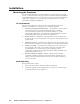
Precautions Safety Instructions • English Warning This symbol is intended to alert the user of important operating and maintenance (servicing) instructions in the literature provided with the equipment. Power sources • This equipment should be operated only from the power source indicated on the product. This equipment is intended to be used with a main power system with a grounded (neutral) conductor. The third (grounding) pin is a safety feature, do not attempt to bypass or disable it.
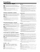
Quick Start — PIP 422 and PIP 444 Installation Step 5 Step 1 Output connectors — Connect a component video, S-video, and/or composite video display device to the rear panel Output BNC connectors (5). For tabletop placement, install the four rubber feet on the bottom of the PIP picture-in-picture processor. Otherwise, mount the processor in a rack using the included rack ears or install the processor in furniture.
Quick Start — PIP 422 and PIP 444, cont’d Step 7 Configure the output RS-232/422 connector — For optional remote control of the PIP, connect a host computer or third party controller to the rear panel RS-232/ RS-422 female 9-pin D connector (7). 1. Press Menu until the LCD reads Output Config. 2. Press Next. 7 3. Rotate either Adjust knob to select the output format (NTSC or PAL).
Table of Contents Chapter 1 • Introduction ...................................................................................................... 1-1 About the Picture-in-Picture Processors .............................................................. 1-2 Features ................................................................................................................................... 1-2 Chapter 2 • Installation ....................................................................................
Table of Contents, cont’d Chapter 4 • Remote Control .............................................................................................. 4-1 Simple Instruction Set Control .................................................................................. 4-2 Host-to-PIP communications ............................................................................................ 4-2 PIP-initiated messages .............................................................................................
PIP 422 and PIP 444 Picture-in-Picture Processors 1 Chapter One Introduction About the Picture-in-Picture Processors Features
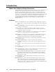
Introduction, cont’d Introduction About the Picture-in-Picture Processors The Extron PIP 422 is a 2-input video picture-in-picture processor. The PIP 444 is a 4-input picture-in-picture video processor. The processors accept up to two (PIP 422) or four (PIP 444) composite video, S-video, or component video input signals. Both units can output the signals simultaneously to three displays: one composite, one S-video, and one component. Both PIPs feature window effects and freeze control.
PIP 422 and PIP 444 Picture-in-Picture Processors 2 Chapter Two Installation Mounting the Processor Rear Panel Connections Setting Up Genlock and Vertical Interval Switching
Installation, cont’d Installation Mounting the Processor The PIP 422 and PIP 444 are housed in 1U high, 17.4" wide metal enclosures that are rack- or desk-mountable. The appropriate rack/desk mounting kit (#70-077-03) is included with the processor. The processor may also be surface-mounted under a table, desk, or podium, or on a wall, using an optional Extron 1U enclosure under-desk mounting kit (#70-222-01).
Mounting Screws (2 Plcs) Each Side Supplied Rack Mounting Bracket or #8 Screw (4 Plcs) Each Side Optional Furniture Mounting Bracket Figure 2-1 — Mounting a PIP 3. Insert the processor into the rack, align the holes in the mounting bracket with those of the rack. 4. Secure the processor to the rack using the supplied machine screws. Table or wall mounting The table/wall mounting brackets extend approximately 1/4" (6.4 mm) above the top surface of the processor enclosure.
Installation, cont’d Through-desk mounting Mount the PIP through a desk or podium as follows: 1. Remove the feet from the underside of the PIP, if installed. 2. Attach the supplied mounting brackets to the processor with the machine screws provided (figure 2-1). 3. Cut the proper sized hole in the mounting surface (figure 2-2). Figure 2-2 — Through desk mounting a PIP 2-4 4. Hold the processor with the attached brackets against the underside of the table or other furniture.
Rear Panel Connections 2 100-240V 0.3A 1 R-Y 2 Y/VID B-Y/C 2 R-Y Y/VID B-Y/C O U T P U T S I N P U T S VIDEO Y C RS-232/422 R-Y V B-Y 50/60 Hz 3 1 3 4 6 Figure 2-3 — PIP 422 rear panel 2 100-240V 0.
Installation, cont’d 3 Input loop-through (bottom) connectors — If desired, connect local monitors to these female BNC connectors. The processor buffers the video input and loops it out on these connectors. The processor does not alter the video signal between the input and the buffered loop-through in any way. The processor’s buffered loop-through output is in the same format as the input.
Setting Up Genlock and Vertical Interval Switching For vertical interval switching (to allow clean switching between signals from several devices during the vertical blanking period of each signal), a composite sync signal can be applied at the Genlock In connector, and also passed to another device via the Genlock Out connector. If the genlock connectors are used only for vertical interval switching, no horizontal or subcarrier phase adjustments are required.
Installation, cont’d 8. View the horizontal phases again. If the phase difference is not zero, repeat steps 6 and 7 until the settings do not change. 9. Once the settings are stable, disconnect the oscilloscope, and reconnect the genlock cables. 10. Check the display(s) for proper colors and for undesirable artifacts in the image(s). Make adjustments as necessary. 11. If other PIPs are part of this genlock daisy chain, connect the oscilloscope to each device, and repeat this procedure.
340 350 0 10 20 30 330 40 320 50 310 60 300 70 290 280 80 270 90 260 100 250 110 240 120 230 130 220 140 210 150 200 190 180 170 160 Figure 2-8 — Vectorscope screen during horizontal phase adjustment Figure 2-9 below shows an example of a view of a vectorscope during adjustment of the color subcarrier phase (SC/H). The subcarrier phase should be aligned to 0º (indicated in the figure by the triangle).
Installation, cont’d 2-10 PIP 422 and PIP 444 Picture-in-Picture Processors • Installation
PIP 422 and PIP 444 Picture-in-Picture Processors 3 Chapter Three Operation Front Panel Features Power-on Indications Menu System Picture Controls Window Presets Additional Functions Optimizing the Image
Operation, cont’d Operation Front Panel Features PIP 422 PICTURE-IN-PICTURE PROCESSOR WINDOW PRESETS INPUTS FREEZE 1 2 SWAP PRESET ENTER PICTURE CONTROLS WINDOW SELECT COL/TINT BRT/CONT DETAIL POSITION 1 1 2 2 1 2 3 4 5 SIZE ZOOM MENU NEXT ADJUST 6 7 8 9 Figure 3-1 — PIP 422 front panel features PIP 444 PICTURE-IN-PICTURE PROCESSOR WINDOW PRESETS INPUTS FREEZE 1 2 3 4 PRESET ENTER PICTURE CONTROLS WINDOW SELECT COL/TINT BRT/CONT DETAIL POSITION 1 2 1 2 3 4 3 4 1 2
6 Picture Control buttons — The Picture Control buttons select individual and Adjust knobs image adjustments that are adjusted using the Adjust ( 9 ). • Color/Tint control button — The Color/Tint button selects the display color and tint adjustments. See “Picture Controls” in this chapter. Tint control is not available for PAL inputs. • Brightness/Contrast control button — The Brightness/Contrast button selects the display brightness and contrast adjustments. See “Picture Controls” in this chapter.
Operation, cont’d Power-on Indications Power is automatically applied when the power cord is connected to an AC source. When AC power is applied, the switcher performs a self-test that blinks all of the front panel LEDs and then lights only the LEDs for the inputs previously selected for the display. The self-test also displays the model name, part number, and the firmware version in the LCD display.
Menu System Menu system overview Figure 3-4 shows a flowchart of the main menu system. Power on Extron, Inc. PIP 444 (422) 2 sec. 60-606 (607) -01 2 sec. FW ver. n.nn Default Cycle Menu NOTE The PIP returns to the last active main menu or submenu when you press Menu. Input Config 20 sec. Menu Output Config 20 sec. Menu Advanced Config 20 sec. Menu Genlock Config* 20 sec. Menu Menu To exit menu press NEXT *PIP 444 only 20 sec.
Operation, cont’d Input Configuration menu Figure 3-5 is a flowchart that shows an overview of the Input Configuration menu and the available settings. Default Cycle 20 sec. Menu NOTE The PIP returns to the last active main menu or submenu when you press Menu. 20 sec.
Output Configuration menu Figure 3-6 is a flowchart that shows an overview of the Output Configuration menu and the available settings. Default Cycle 20 sec. Menu NOTE The PIP returns to the last active main menu or submenu when you press Menu. 20 sec.
Operation, cont’d Advanced Configuration menu Figure 3-7 is a flowchart that shows an overview of the Advanced Configuration menu, the submenus, and the available settings. The Advanced Configuration menu has four submenus that allow you to view and select the border color, background color, window transition effect, priority, and anti-aliasing mode for the windows and a fifth submenu that displays the device’s temperature. Rotate either of the Adjust knobs to select settings from each of the submenus.
Window Effect submenu Use this submenu to select a transition effect for the PIP to use when enabling, disabling, or swapping windows. You can choose from the following three options: Cut — The window turns seamlessly on and off. No effect is applied to the transition. This is the default setting. Wipe — The window appears to unroll over the old screen, from left to right. Dissolve — The window appears to dissolve on or off. The wipe and dissolve effects are set to a fixed 0.
Operation, cont’d Exit menu From the Exit menu (figure 3-9), press the Next button to return to the default display cycle, or press the Menu button to return to the Input Configuration menu. Default Cycle Menu NOTE The PIP returns to the last active main menu or submenu when you press Menu. 20 sec.
Extron, Inc. PIP 444 (422) Power on 2 sec. 60-606 (607) -01 2 sec. FW ver. n.nn Display Cycle WINDOW SELECT 1 2 3 4 BRT/CONT COL/TINT Color 063 Tint 031 Bright 063 Cont 031 DETAIL POSITION SIZE ZOOM Detail 07 H WinPos V 045 007 H Win Size V 024 063 H Win Zoom V 024 053 20 sec. timeout Anti-aliasing mode • Off* • Mode 1 • Mode 2 • Mode 3 • Auto DETAIL POSITION SIZE ZOOM Antialiasing Auto H ImgPos V +045 –007 H Img Size V –024 +063 H Img Zoom V +024 –053 * Default 20 sec.
Operation, cont’d 4. Rotate the Adjust knob or Adjust following adjustment ranges: knob to vary the settings within the The Adjust knobs have no mechanical limits to their rotation. • Color/Tint: The range for both adjustments is 0 to 127. • Brightness/Contrast: The range for brightness is 50 to 127. The range for contrast is 38 to 107. • Filter: Push the Detail button to toggle between the detail filter adjustment and the anti-aliasing adjustment.
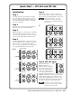
Auto-center the image To automatically center the image within the currently selected window, press and hold the Position and Size buttons for approximately half a second. The auto-center function does not work if the image size is set extremely small, relative to the window size. Window Presets The PIP 422 has 10 preset slots that save settings for the number, size, position, priority, text and colors of the windows’ borders and background. The PIP 444 has 20 preset slots.
Operation, cont’d Input 1 Input 2 Input 1 Input 3 Input 2 Input 3 Input 4 1 2 3 4 Input 2 Input 1 Input 4 Input 4 5 Input 1 Input 1 Input 1 Input 3 6 Input 2 Input 3 Input 4 Input 2 7 8 Input 2 Input 2 Input 1 Input 1 Input 1 Input 3 Input 4 Input 3 9 10 Input 2 Input 2 Input 1 Input 3 Input 4 Input 2 12 11 Input 1 Input 1 Input 1 Input 3 Input 2 Input 3 Input 4 13 14 Input 2 Input 3 Input 2 15 Input 2 Input 3 Input 2 Input 3 Input 2 Input 4 Input 2 I
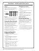
Additional Functions Freeze mode The PIP 444’s Freeze mode lets you freeze an input to the current image. When frozen, the image is saved in the PIP’s memory and will not be lost if you disconnect the input. To freeze an input’s window in the currently-displayed image, simultaneously press the Freeze button and the desired input’s selection button (figure 3-13). The LED for the input lights. Repeat to unfreeze the window. Recalling a preset or adjusting the size of a frozen image unfreezes the image.
Operation, cont’d Unit reset To reset the PIP to its factory default settings, press and hold the Menu and Next buttons while you power up the processor (figure 3-15). The LCD panel displays the message System Reset for two seconds and then begins the default display cycle. Press and hold both buttons simultaneously while applying power. MENU NEXT SYSTEM RESET Power 2 sec. Extron, Inc. PIP 444 (422) 2 sec. NOTE The front panel reset also returns the firmware to the factory default.
2. Release the Freeze and Preset buttons. 3. To change the baud rate, rotate either Adjust knob. 4. Press and release the Next button. The LCD displays the serial port protocol. 5. To change the serial port protocol, rotate either Adjust knob. 6. Press and release the Menu button or wait approximately 20 seconds. The processor reverts to the default display cycle.
Operation, cont’d k. Vertical window positioning — Press the Position button and then rotate the Adjust knob to move the top edge of the selected window to the desired location. Keep in mind that sizing the window vertically moves the bottom edge of the window only. l. Vertical image positioning within the window — Press the Position button a second time and then rotate the Adjust knob to move the top edge of the image in the selected window to the desired location. m.
PIP 422 and PIP 444 Picture-in-Picture Processors 4 Chapter Four Remote Control Simple Instruction Set Control Control Software for Windows®
Remote Control, cont’d Remote Control The PIP’s RS-232/422 port is used to connect to a host or external controlling device, such as a computer or control system, which can generate the proper command codes and recognize the processor’s responses. The cable used to connect the RS-232/RS-422 port to a computer or control system may need to be modified by removing pins or cutting wires. If unneeded pins are connected, the processor may hang up.
Using the command/response tables The command/response table is shown beginning on page 4-5. Symbols, defined on page 4-4 are used throughout the table to represent variables in the command/ response fields. An ASCII-to-hexadecimal (HEX) conversion table is provided below. Symbol definitions are provided below. Command and response examples are shown throughout the command/response table.
Remote Control, cont’d Symbol Definitions = CR/LF (carriage return/line feed) (hex 0D 0A) • = Carriage return (no line feed, hex 0D) = Space character Esc = Escape key (hex 1B) X1 = Input number (1 - 2, PIP 422; 1 - 4, PIP 444): 1 = Input 1 2 = Input 2 X2 3 = Input 3 4 = Input 4 = Firmware build number (4 digits, 0001 – 9999) X20 = Temperature in degrees Fahrenheit* X21 = Temperature in degrees Celsius* X22 = Output standard: 2 = NTSC 0 IRE X23 = Color/tint value (000 – 127) = Brightness ran
Command/response table for SIS commands Command ASCII Command Response (host to PIP) (PIP to host) Additional description Window mute Blank window Enable window View window status X1 *1B X1 *0B Blk X1 *0 Blk X1 *1 X1 B X2 Turn window Turn window X1 X1 off. on. Swap (PIP 422 only) Swap main and PIP windows % Tke0 Swap the main and PIP windows. Typ X1 * X3 Set video format for input X1 to X3 . Set video format for input 1 to S-video. Show video signal type for input X1 .
Remote Control, cont’d Command/response table for SIS commands (cont’d) Command ASCII Command Response (host to PIP) (PIP to host) Additional description Horizontal shift For the image shift command, a negative (–) value is a left shift and a positive value (+) is a right shift. To enter a negative value for the image positioning, enter a minus sign before the X9 value. Entry of a positive sign is optional, but not required; if no sign is included in the SIS command, the PIP assumes a positive value.
Command/response table for SIS commands (cont’d) Command ASCII Command Response (host to PIP) (PIP to host) Additional description Vertical size For the image size command, a negative (–) value shrinks the image and a positive value (+) enlarges the image. To enter a negative value for the image size, enter a minus sign before the X12 value. Entry of a positive sign is optional, but not required; if no sign is included in the SIS command, the PIP assumes a positive value.
Remote Control, cont’d Command/response table for SIS commands (cont’d) Command ASCII Command Response (host to PIP) (PIP to host) Additional description Front panel lockout (Executive mode) Lock front panel 1X Exe1 Unlock front panel 0X Exe0 View front panel lock status X X2 Lock front panel picture control and menu system adjustments, RS-232/422 adjustments only. All adjustments and selections can be made from the front panel. Show executive mode status.
Command/response table for special function SIS commands The syntax for setting a special function is Xn * X? # where Xn is the value or variable (such as 1 in the first example below), X? is the function number (such as “Set text location” in the first example below), and # is the execute command. To view a function’s setting, use X? # where X? is the function number.
Remote Control, cont’d Command/response table for special function SIS commands (cont’d) Command ASCII Command Response (host to PIP) (PIP to host) Additional description Window anti-aliasing filter Set anti-aliasing filter X1 * X27 *7# Example: 3*4*7# View anti-aliasing mode Aaf X1 * X27 Aaf3*4 X1 *7# X27 Set anti-aliasing filter for window X1 to mode X27 . Set anti-aliasing filter for window 3 to auto-adjust. View anti-aliasing filter for window X1 .
2. Click the Software tab (figure 4-2). 3. Scroll to the desired program and click Install (figure 4-3). Figure 4-3 — Software installation Follow the on-screen instructions. By default, the Windows installation of the PIP 422 & 444 Control Program creates a C:\Program Files\Extron\ PIP 422 & 444 directory, and it places four icons into a group folder named “Extron Electronics\PIP 422 & 444.” The four installed icons are: 4.
Remote Control, cont’d If you don’t want to take this step every time, select the Automatically connect with this setting when it starts up next time check box. The PIP 422 & 444 program window appears (figure 4-5). Figure 4-5 — PIP 422 & 444 program window The program window is divided into three areas: a tool bar on the top of the window, a graphic area on the right side of the window, and a controls area on the left side of the window.
Tool bar The tool bar (figure 4-6) provides a number of buttons that provide shortcuts for common tasks such as connecting and disconnecting, saving and recalling the current configuration, uploading new firmware, and system help. Saving and restoring the current configuration and uploading firmware are covered in more detail below.
Remote Control, cont’d 3. Click the update firmware button (figure 4-8). The Extron Firmware Loader appears. Figure 4-8 — Open window 4a. Click Browse. The open file window appears. 4b. Navigate to the folder where you saved the firmware upgrade file. Select the file. The Firmware Loader returns to the top. Ensure that the firmware upgrade is for the PIP. Valid PIP firmware files must have the file extension “.pkg”. Any other file extension is not a firmware upgrade for your PIP. 4c. Click Upload.
Check for software updates button This button forces the controlling computer, if connected to the Internet, to check the Extron Web site to see if any firmware update (firmware of a version newer than that installed in the PIP) is available for the PIP. If a newer firmware version is available, the program prompts you to download and install the firmware.
Remote Control, cont’d Controls area The controls area, figure 4-10, consists of four tabs, Control, Preset, Picture, and Advanced, that allow you to perform many of the same functions as the PIP’s front panel. Figure 4-10 — Controls area, Control tab Control tab Figure 4-10 shows the controls area with the Control tab selected. 4-16 • Windows Enable — Select and deselect a window for display by clicking the associated window’s button.
Preset tab Figure 4-11 shows the controls area with the Preset tab selected. Figure 4-11 — Controls area, Preset tab • Preview — To see a preset’s settings without recalling the preset, select the desired preset using the drop box and click the Preview button. The program pops up a window that resembles the graphic area (figure 4-9). The graphic area displayed as a result of the Preview function is for display only. The settings cannot be changed on this screen.
Remote Control, cont’d Picture tab Figure 4-12 shows the controls area with the Picture tab selected. Figure 4-12 — Controls area, Picture tab • Picture Controls — The picture controls allow you to set the input video format, anti-aliasing filter, color, tint, contrast, brightness, and detail filter for each window. To set a picture control, select the desired window using the Window Select drop box and set the desired value.
Advanced tab Figure 4-13 shows the controls area with the Advanced tab selected.
Remote Control, cont’d 4-20 PIP 422 and PIP 444 Picture-in-Picture Processors • Remote Control
PIP 422 and PIP 444 Picture-in-Picture Processors A Appendix A Specifications and Part Numbers Specifications Part Numbers
Specifications andand PartPart Numbers, cont’d Specifications Numbers Video Gain ............................................... Unity Differential phase error .............. 1.5º at 3.58 MHz and 4.43 MHz Differential gain error ................. 1.5% at 3.58 MHz and 4.43 MHz Video input and loop-through Number/signal type PIP 444 ............................... 4 component video, S-video, composite video inputs 4 identical, buffered loop-throughs PIP 422 ...............................
Sync Genlock connectors (PIP 444) .... 1 BNC female for genlock input 1 BNC female for genlock output (terminate with 75 ohms if unused) Standards Input .................................. NTSC 3.58, NTSC 4.43, PAL, SECAM Output ............................... NTSC 3.58, PAL Control/remote — processor Serial control port ........................ RS-232 or RS-422, 9-pin female D connector Baud rate and protocol ...............
Specifications and Part Numbers, cont’d Part Numbers Included parts These items are included in each order for a PIP 422 or PIP 444: Included parts Replacement part number PIP 444 60-606-01 PIP 422 60-607-01 Rack/desk mounting brackets 70-077-03 IEC power cord Rubber feet (self-adhesive) (4) User’s manual Label holder (self-adhesive) Extron Software Products CD, disk B Accessories These items may be ordered separately: Accessories A-4 Part number MBD 149 Under-desk mounting kit 70-077-03 SVHSF
FCC Class A Notice Note: This equipment has been tested and found to comply with the limits for a Class A digital device, pursuant to part 15 of the FCC Rules. These limits are designed to provide reasonable protection against harmful interference when the equipment is operated in a commercial environment. This equipment generates, uses and can radiate radio frequency energy and, if not installed and used in accordance with the instruction manual, may cause harmful interference to radio communications.
www.extron.com Extron Electronics, USA 1230 South Lewis Street Anaheim, CA 92805 800.633.9876 714.491.1500 FAX 714.491.1517 Extron Electronics, Europe Beeldschermweg 6C 3821 AH Amersfoort, The Netherlands +800.3987.6673 +31.33.453.4040 FAX +31.33.453.4050 Extron Electronics, Asia 135 Joo Seng Rd. #04-01 PM Industrial Bldg., Singapore 368363 +800.7339.8766 +65.6383.4400 FAX +65.6383.4664 © 2007 Extron Electronics. All rights reserved.