User’s Manual P/2 DA2 WM/EC and AAP models Distribution Amplifier Extron Electronics, USA 1230 South Lewis Street, Anaheim, CA 92805 800.633.9876 714.491.1500 FAX 714.491.1517 USA Extron Electronics, Europe Beeldschermweg 6C, 3821 AH Amersfoort +31.33.453.4040 FAX +31.33.453.4050 The Netherlands Extron Electronics, Asia 135 Joo Seng Rd. #04-01, PM Industrial Bldg. +65.383.4400 FAX +65.383.4664 Singapore 368363 Extron Electronics Information ExtronWEB™: www.extron.com ExtronFAX™: 714.491.
Precautions Safety Instructions • English This symbol is intended to alert the user of important operating and maintenance (servicing) instructions in the literature provided with the equipment. This symbol is intended to alert the user of the presence of uninsulated dangerous voltage within the product's enclosure that may present a risk of electric shock. Caution Read Instructions • Read and understand all safety and operating instructions before using the equipment.
Table of Contents Chapter 1 • Introduction ......................................................... 1-1 About the P/2 DA2 WM/EC and P/2 DA2 WM/EC AAP ............................................................. 1-2 Features ...................................................................................... 1-2 Chapter 2 • Controls and Installation ........................... 2-1 Front and Rear Panels ................................................. 2-2 Front faceplate ............................
P/2 DA2 WM/EC 1 Chapter One Introduction About the P/2 DA2 WM/EC and P/2 DA2 WM/EC AAP Features P/2 DA2 WM/EC Table of Contents P/2 DA2 WM/EC Table of Contents
Introduction About the P/2 DA2 WM/EC and P/2 DA2 WM/EC AAP The P/2 DA2 WM/EC and P/2 DA2 WM/EC AAP are a one input, two output, high resolution VGA/XGA distribution amplifier with audio. With a video bandwidth of 300 MHz, this distribution amplifier is compatible with VGA, SVGA, VESA, XGA, and SXGA graphics cards, monitors, projectors, and LCD panels. For audio, the P/2 DA2 WM/EC features a 3.5 mm female jack for input and a 3.5 mm captive screw connector for balanced or unbalanced output.
Controls and Installation Unity – output signal level is same as that of input with no added peaking Front and Rear Panels Front faceplate 50% – increases the output signal level and adds 50% of the maximum peaking to the signal If the edges of the image seem to exceed their boundaries, or if thin lines and sharp edges look thick and fuzzy, try changing the level/peak setting.
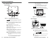
Controls and Installation, cont’d “Euro Channel installation” section. Installing the P/2 DA2 WM/EC Easy setup procedure The wall-mounted P/2 DA2 WM kit consists of the faceplate/distribution amplifier assembly and a mounting bracket which mounts in a wall opening and to which the faceplate assembly is attached. The P/2 DA2 EC kit consists of the faceplate/distribution amplifier assembly which mounts in the Euro Channel raceway. 1 2 3 4 6 Power up all of the input and output devices.
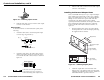
Controls and Installation, cont’d Cabling Connecting audio output The P/2 DA2 WM cabling diagram below shows how to connect input and output devices to the distribution amplifier ’s front panel. The P/2 DA2 EC model has identical connectors. Before connecting audio output, determine whether your audio system is unbalanced or balanced. Then, follow the instructions below to connect unbalanced audio, or the instructions for “Balanced audio” to connect balanced audio.
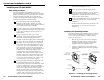
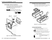
Controls and Installation, cont’d 3. Slide the audio cable connector into the audio output connector on the interface. Installing Architectural Adapter Plates Figure 2-6 — Fastening captive screws 3. Slide the audio cable connector into the audio output connector on the interface. Balanced audio To attach the interface to a balanced audio system, do the following: 1. The P/2 DA2 WM AAP may have up to 4 optional adapter plates and the P/2 DA2 EC AAP can have up to 3 adapter plates.
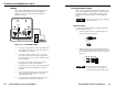
Controls and Installation, cont’d P/2 DA2 EC Euro Channel installation 2 DA P/2 WM N/ G GAI AKIN PE1 50 U N D S R ED NITO O ER FF M BU CAL LO DIO AU A TO AU P TM PINS ID 4 11 The center pole of the power input connector contains no conductor. Connect the conductors to the two outer poles only, exactly as shown here.
Controls and Installation, cont’d OFF — Set both pins to Off if you are attaching a local monitor to the P/2 DA2 WM/EC.
Appendix P/2 DA2 WM/EC Specifications Video input Number/signal type ................... 1 VGA/SVGA/XGA/SXGA RGBHV, RGBS, RGsB, RsGsBs Connectors .................................... 1 15-pin HD male Nominal level(s) .......................... Analog ....... 0.7V p-p Minimum/maximum level(s) .... Analog ....... 0.4V to 2.0V p-p with no offset Impedance .................................... 75 ohms Horizontal frequency .................. Autoscan 15 kHz to 135 kHz Vertical frequency .......................
Appendix, cont’d P/2 DA2 WM Faceplate Dimensions Dimensions of the P/2 DA2 WM and its AAP version are provided here for those who wish to make their own customized faceplate. The following diagrams are not drawn to scale. HAND SAND TO 0.06" RADIUS AROUND THE TOP OF THESE EDGES. THRU .120 THRU .210 THRU .210 THRU DETAIL A Figure A-2 — WM model AAP faceplate dimensions DETAIL A All dimensions are given in inches. Figure A-1 — WM model faceplate dimensions All dimensions are given in inches.
Appendix, cont’d Cables Optional Architectural Adapter Plates The table below lists various lengths of high resolution VGA cables which can be used with the P/2 DA2 WM/EC.
P/2 DA2 WM/EC Appendix P/2 DA2 WM/EC Appendix A-9 Adapter plate description Plate size Front connector type Rear connector type Part # Gray Blank plate 1 1 n.a. n.a. 70-090 -01 -11 -21 Blank plate 2 2 n.a. n.a.
A-10 Plate size 1 2 1 1 1 1 Adapter plate description 1 S-video female and 1 BNC female 1 S-video female and 3 RCA female 1 S-video female and 2 RCA female 1 BNC female and 2 RCA female 1 BNC female and 1 3.5mm mini stereo jack P/2 DA2 WM/EC Appendix 1 RCA female and 1 3.5mm mini stereo jack -02 -01 70-108 70-108 70-109 BNC female and RCA female BNC female and RCA female RCA female and 3.
A-12 P/2 DA2 WM AAP Mounting Template (shown in actual size) The dashed line indicates the recommended cut-out area (3.875” H x 7.525” W) for the installation surface. The solid, outer line (4.50” H x8.325” W) represents the outside edge of the wall mounting bracket.