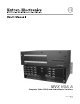
MVX VGA A Computer Video (VGA) and Audio Matrix Switchers 68-521-31 Rev.
Precautions Safety Instructions • English Warning This symbol is intended to alert the user of important operating and maintenance (servicing) instructions in the literature provided with the equipment. Power sources • This equipment should be operated only from the power source indicated on the product. This equipment is intended to be used with a main power system with a grounded (neutral) conductor. The third (grounding) pin is a safety feature, do not attempt to bypass or disable it.
FCC Class A Notice N This equipment has been tested and found to comply with the limits for a Class A digital device, pursuant to part 15 of the FCC Rules. These limits are designed to provide reasonable protection against harmful interference when the equipment is operated in a commercial environment. This equipment generates, uses and can radiate radio frequency energy and, if not installed and used in accordance with the instruction manual, may cause harmful interference to radio communications.
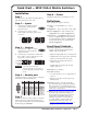
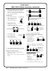
Quick Start — MVX VGA A Matrix Switchers Installation Step 6 — Power Step 1 Plug the switcher into a grounded AC source. Turn off power to the input and output devices, and disconnect their power cords. Definitions Tie — An input-to-output connection Step 2 — Inputs b. Set of ties — An input tied to two or more outputs Connect up to 16 high resolution video inputs to the 15-pin HD input connectors.
Quick Start — MVX VGA A Matrix Switchers, continued RGBHV and Audio buttons select and deselect video and/or audio. The Audio LED blinks to indicate audio breakaway. The Audio button also selects the audio level/adjust mode. See “Viewing and adjusting the audio level” in the next column. Creating a tie 1. Press and release the Esc button to clear any input LEDs, output LEDs, or control LEDs that may be lit. Save a preset Press and hold. 2 seconds Preset LED blinks.
Table of Contents Chapter One • Introduction ........................................................................................................ 1-1 About this Manual ..................................................................................................................... 1-2 About the MVX VGA A Matrix Switchers . ................................................................... 1-2 Definitions . .............................................................................................
Table of Contents, cont’d Setting the front panel locks (Executive modes) ................................................................ 3-36 Selecting Lock mode 2 or toggling between mode 2 and mode 0 ................................. 3-36 Selecting Lock mode 2 or toggling between mode 2 and mode 1 ................................. 3-37 Performing a system reset from the front panel ................................................................
Appendix A • Specifications, Part Numbers, Accessories ................................ 5-15 Specifications ............................................................................................................................... A-2 Part Numbers and Accessories .......................................................................................... A-5 MVX matrix switcher part numbers ....................................................................................... A-5 Included parts ........
PRELIMINARY Table of Contents, cont’d All trademarks mentioned in this manual are the properties of their respective owners.
1 Chapter One Introduction About this Manual About the MVX VGA A Matrix Switchers Definitions Features PRELIMINARY MVX VGA A Matrix Switchers
Introduction About this Manual This manual contains installation, configuration, and operating information for the Extron MVX VGA A wideband computer video (VGA) and audio matrix switchers. About the MVX VGA A Matrix Switchers The MVX matrix switchers distribute any input signal to any combination of outputs. The matrix switchers can route multiple input/output configurations simultaneously.
The MVX A switchers input and output VGA video on 15-pin HD connectors and audio on 3.5 mm, 5-pole captive screw terminals. The audio switching can either be linked with the video (audio follow) or be independent of the video (audio breakaway). Adjustable input audio gain and attenuation compensates for level differences between audio inputs.
Introduction, cont’d Features Video — The switchers input and output RGBHV or RGBS (VGA) video on 15-pin HD connectors. They can also switch RGsB, RsGsBs, component/ HDTV, S-video, or composite video. Bandwidth — The MVX switchers provide a minimum of 300 MHz (-3 dB) video bandwidth, fully loaded. Audio inputs — The switchers input and output balanced or unbalanced stereo audio on 3.5 mm, 5-pole captive screw terminals.
Upgradeable firmware — The firmware that controls all switcher operation can be upgraded in the field via either serial port, without taking the switcher out of service. Firmware upgrades are available for download on the Extron Web site, www.extron.com, and can be installed using the Windows-based control program. Labeling — The Extron button label software ships with every Extron matrix switcher.
PRELIMINARY Introduction, cont’d 1-6 MVX VGA A Matrix Switchers • Introduction
2 Chapter Two Installation Mounting the Switcher Rear Panel Cabling and Views Front Panel Configuration Port PRELIMINARY MVX VGA A Matrix Switchers
Installation Mounting the Switcher UL requirements PRELIMINARY The following Underwriters Laboratories (UL) requirements pertain to the installation of the MVX into a rack (figure 2-1). 1. Elevated operating ambient temperature — If the equipment installed in a closed or multi-unit rack assembly, the operating ambient temperature of the rack environment may be greater than room ambient temperature.
Rear Panel Cabling and Views Figure 2-1 shows the rear panel of the MVX 128 A. 1 2 COMPUTER OUT 5 7 9 11 1 3 5 7 2 4 6 8 10 12 2 4 6 8 INPUTS 2 3 4 5 6 8 OUTPUTS 7 9 8 10 11 12 1 2 3 4 5 4 6 7 8 REMOTE LISTED 1T23 I.T.E.
Installation, cont’d Video connections N The matrix switcher does not alter the video signal in any way. The signal output by the switcher is in the same format as the input. N The MVX matrix switchers can also switch RGBS, RGsB, RsGsBs, component video, S-video, or composite video with the appropriate adapters. a RGB video inputs — Connect the analog computer-video sources to these 15-pin HD female connectors.
Audio connections By default, the audio ties follow the video ties. Audio breakaway, which can be activated via the front panel or under serial port control, allows you to select from any one of the audio input sources and route it separately from its corresponding video source. See chapter 3, “Operation”, chapter 4, “Programmer’s Guide”, and chapter 5, “Matrix Software”, for details. Connections for balanced and unbalanced audio inputs — Each input has a 3.
Installation, cont’d e Connections for balanced and unbalanced audio outputs — These 3.5 mm, 5-pole captive screw connectors output the selected unamplified, line level audio. Connect audio devices, such as an audio amplifier or powered speakers. See figure 2-6 to properly wire an output connector. Use the supplied tie-wrap to strap the audio cable to the extended tail of the connector. NO GROUND HERE.
Reset button g Reset button — The Reset button initiates two levels of reset to the matrix switcher. For the two different reset levels, press and hold the button while the switcher is running or while you power up the switcher. RESET See “Rear Panel Operations” in • Rear panel (mode 5) system reset — Press and hold the Reset button until the Reset LED blinks three times (approximately 9 seconds), then release the button and press it again.
Installation, cont’d Front Panel Configuration Port CONTROL ENTER PRESET IO VIEW ESC RGBHV AUDIO CONFIG MVX SERIES VGA MATRIX SWITCHER WITH ADSP TM 9 Figure 2-8 — Front panel configuration port PRELIMINARY i Configuration port — This 2.5 mm mini stereo jack serves the same serial communications function as the rear panel Remote port, but it is easier to access after the matrix switcher has been installed and cabled. The optional 9-pin D to 2.
3 Chapter Three Operation Front Panel Controls and Indicators Front Panel Operations Rear Panel Operations Optimizing the Audio Troubleshooting Configuration Worksheets PRELIMINARY MVX VGA A Matrix Switchers
Operation N On some MVX switchers, the video selection button is labeled “Video” rather than “RGBHV”. Front Panel Controls and Indicators The front panel controls (figure 3-1) are grouped into two sets. The input and output buttons are grouped on the left side of the control panel. The control buttons and video/audio (I/O) selection buttons are grouped on the right side of the panel. N The MVX 128 A has a similar front panel configuration, but with fewer input buttons and output buttons.
Input and output buttons N If the switcher has fewer inputs or outputs than input or output buttons, only the buttons for which the switcher has an input or output perform the function of selecting and identifying that input or output. b c Input buttons and LEDs — The input buttons and LEDs have two primary functions (•) and two secondary functions (❏): • Select an input. • Identify the selected input. ❏ Select a preset. See “Using global presets” on page 3-21. ❏ Display the output volume level.
Operation, cont’d Control buttons d Enter button and/or LED — The Enter button and LED have three primary functions (•) and four secondary functions (❏): • Saves changes that you make on the front panel. To create a simple configuration: PRELIMINARY e 3-4 Specify RGBHV, audio, or both (see I/O selection buttons [h] and [i]). Press the desired input button (a). Press the desired output button(s) (b). Press the Enter button.
f View (<) button and/or LED — The View (<) button and LED have two primary functions (•) and six secondary functions (❏): • Selects a View-only mode that displays the current configuration. g • Indicates that View-only mode is active. ❏ Decreases the audio level of the selected input. See “Viewing and adjusting the input audio level” on page 3-25. ❏ Indicates a negative (attenuation) audio level. See “Viewing and adjusting the input audio level” on page 3-25.
Operation, cont’d I/O controls You must specify video, audio, or both when you are creating or viewing a configuration. This is done with the RGBHV button (h) and Audio (i) buttons. N On some MVX switchers, the video selection button is labeled “Video” rather than “RGBHV”. PRELIMINARY h i 3-6 RGBHV button and/or LED — The RGBHV button and LED have two primary functions (•) and five secondary functions (❏): • Selects and deselects video for a configuration that is being created or viewed.
Front Panel Operations • Creating ties, sets of ties, and configurations • Changing a configuration • Viewing ties, sets of ties, and configurations • Muting and unmuting outputs • Saving a preset • Recalling a preset • Viewing and adjusting the output volume • Viewing and adjusting the input audio level • Locking the front panel • Performing resets from the front panel • Reading and setting the RS-232/RS-422 Remote port settings Front panel security lockouts In the procedural descript
Operation, cont’d Creating a configuration The current configuration can be changed using the front panel buttons. Change the current configuration as follows: 1. Press the Esc button to clear any input LEDs, output LEDs, or control LEDs that are lit. 2. Select to configure video, audio, or both by pressing the RGBHV button and/or Audio button. 3. Select the desired input and output(s) by pressing the input and output buttons.
Example 1: Creating a set of video and audio ties In the following example, input 5 is tied to outputs 3, 4, and 8. The steps show the front panel indications that result from your actions. N This example assumes that there are no ties in the current configuration. 1. Press and release the Esc button (figure 3-3). Press the Esc button to clear all selections. CONTROL 1 ENTER PRESET VIEW 1 = LED blinks once. ESC The LED blinks once. 2.
Operation, cont’d 4. Press and release the output 3, output 4, and output 8 buttons (figure 3-6). N The entire set of ties can be canceled at this point by pressing and releasing the Esc button. The Esc LED flashes once. Press and release the Output 3, Output 4, and Output 8 buttons. The buttons blink to indicate that the selected RGBHV and audio input will be tied to these outputs. ENTER PRESE 1 2 3 4 5 OUTPUTS 6 7 8 The Enter LED blinks to indicate the need to confirm the change.
Example 2: Adding a tie to a set of video and audio ties In the following example, a new video tie is added to the current configuration. The steps show the front panel indications that result from your action. N This example assumes that you have performed example 1. 1. Press and release the Esc button (figure 3-9). Press the Esc button to clear all selections. CONTROL 1 ENTER PRESET VIEW = LED blinks once. 1 ESC The LED blinks once.
Operation, cont’d 5. Press and release the Enter button (figure 3-13). Press the Enter button to confirm the configuration change. ENTER The Enter LED and all input LEDs and output LEDs return to the unlit state. Figure 3-13 — Press the Enter button The current configuration (figure 3-14) is now: • Input 5 (video) is tied to output 1, output 3, output 4, and output 8. • Input 5 (audio) is tied to output 3, output 4, and output 8.
Example 3: Removing a tie from a set of video and audio ties In the following example, an existing audio tie is removed from the current configuration. The steps show the front panel indications that result from your action. N This example assumes that you have performed example 1 and example 2. 1. Press and release the Esc button (figure 3-15). Press the Esc button to clear all selections. CONTROL 1 ENTER PRESET VIEW 1 = LED blinks once. ESC The LED blinks once.
Operation, cont’d 4. Press and release the Output 4 button (figure 3-18). Press and release the Output 4 button. The LED blinks to indicate that the selected RGBHV output will be untied. ENTER PRESE 1 2 3 6 4 5 OUTPUTS The Enter LED blinks to indicate the need to confirm the change. Figure 3-18 — Deselect the output 5. Press and release the Enter button (figure 3-19). Press the Enter button to confirm the configuration change.
Viewing a configuration The current configuration can be viewed using the front panel buttons. The View-only mode prevents inadvertent changes to the current configuration. View-only mode also provides a way to mute video and audio outputs (see “Muting and unmuting video and/or audio” on page 3-18). 1. Press the Esc button to clear any input LEDs, output LEDs, or control LEDs that are lit. 2. Press and release the View button. All of the LEDs light for outputs that are not tied. 3.
Operation, cont’d 3. To select both video and audio for viewing, if necessary, press and release the RGBHV button and the Audio button (figure 3-22). I/O In this example, the Audio LED blinks to indicate audio breakaway (assuming you have performed examples 1, 2, and 3). RGBHV AUDIO Press the Audio button to toggle on and off. The LED lights or blinks when selected. Press the RGBHV button to toggle on and off. The LED lights when selected.
Press and release the RGBHV button to deselect RGBHV (figure 3-24). 5. I/O The output buttons for outputs that are tied to input 5 light to indicate audio ties (audio breakaway). RGBHV AUDIO Press the RGBHV The Audio LED remains button to delesect it. lit to indicate that only The LED is unlit audio is selected. when deselected. 2 3 4 5 OUTPUTS 6 7 8 The output buttons for outputs that are not tied to input 5 are unlit.
Operation, cont’d Muting and unmuting video and/or audio Individual outputs can be muted or unmuted as follows: N Mutes are protected when front panel Lock mode 2 is selected. You can view the status of the output (muted or unmuted) in Lock mode 2 but you cannot change it from the front panel. 1. Press the Esc button to clear any input LEDs, output LEDs, or control LEDs that are lit. 2. Press and release the View button. 3.
3. To select both video and audio for viewing and muting, if necessary, press and release the RGBHV button and the Audio button (figure 3-28). N This example shows the indications that the front panel displays if example 1, example 2, and example 3 have been completed. I/O In this example, the Audio LED blinks to indicate audio breakaway (assuming you have performed examples 1, 2, and 3). RGBHV AUDIO Press the RGBHV button to toggle on and off. The LED lights when selected.
Operation, cont’d N If both RGBHV and audio are selected, the muting action toggles both the video and audio outputs. If either the video output or the audio output is already muted, the unmuted output is muted and the muted output is unmuted. N If both RGBHV and audio are selected and only video is muted, the output LED flashes. If only audio is selected, the output LED is lit steadily (indicating no audio mute). 5.
Using global presets N • Only the audio and video ties are stored and recalled; audio gain settings are not saved, and they do not change when a preset is recalled. • Presets cannot be viewed from the front panel unless recalled as the current configuration. Presets can be viewed using Extron’s Windows-based control program. See chapter 5, “Matrix Software”, for more details. • The current configuration and all presets are stored in non-volatile memory.
Operation, cont’d Example 6: Saving a preset The following steps show an example in which the current configuration is saved as a preset. The steps show the front panel indications that result from your actions. 1. Press and release the Esc button (figure 3-34). Press the Esc button to clear all selections. CONTROL 1 ENTER PRESET VIEW = LED blinks once. 1 ESC The LED blinks once. Figure 3-34 — Clear all selections 2.
4. Press and release the Enter button (figure 3-37). The current configuration is now stored in memory location 13 (MVX 128 VGA A) or location 17 (MVX 1212 VGA A, MVX 168 VGA A, MVX 1616 VGA A). Press the Enter button to save the preset. CONTROL ENTER PRESET VIEW ESC All input LEDs return to the unlit state. The Enter and Preset LEDs return to the unlit state. Figure 3-37 — Press the Enter button The following steps show an example in which a preset is recalled to become the current configuration.
Operation, cont’d 3. Press and release the Output 1 button (figure 3-40). Press and release the Output 1 button. The LED blinks to indicate that this preset number is selected but not recalled. 1 1 Preset 13 2 3 4 2 3 4 Preset 14 Preset 15 Preset 16 = Blinking LED CONTROL ENTER PRESET VIEW The Enter LED blinks to indicate the need to recall the preset. The Preset LED remains lit. Figure 3-40 — Select the preset PRELIMINARY 4. Press and release the Enter button (figure 3-41).
Viewing and adjusting the input audio level The audio level of each input can be displayed and adjusted through a range of -18 dB to +24 dB to ensure that there is no noticeable volume difference among sources (figure 3-42). The audio level can be adjusted from the front panel or via serial port control. The default audio level is 0 dB.
Operation, cont’d 5. Press and release the Audio button to exit Audio mode. The Audio LED stops blinking. N • Pressing the Enter or Preset button also exits Audio mode. Pressing the Preset button changes to Recall Preset mode. • There is one audio level setting per input. The audio level setting is shared by the left and right audio inputs. • The audio level settings are stored in non-volatile memory. When power is removed and restored, the audio level settings are retained.
Audio input level settings MVX 1212, 168, 1616 A MVX 128 A 1 2 7 8 +24 View Esc dB 1 2 3 4 5 Output LED 6 7 8 9 10 11 12 View Esc +24 +23 F +23 +22 S +22 +21 S S +21 +20 F +19 S +20 S +19 +18 +18 +17 F +17 +16 S +16 S S +15 +15 +14 F +14 +13 S +13 +12 S +12 +11 F +11 +10 S +10 +9 S S +9 +8 F +8 +7 S +7 +6 PRELIMINARY dB Output LED 3 4 5 6 S +6 +5 F +5 +4 S +4 +3 S S +3 +2 F +2 +1 S +1 0 S 0 -1 S -1 -2 F -2
Operation, cont’d Press and release the Input 5 button (figure 3-45). 3. N Figure 3-45 shows the current level (+8 dB) displayed on the MVX 128 A, an 8-ouput-LED switcher. Press and release the Input 5 button. The LED lights. 1 2 3 4 5 6 4 5 OUTPUTS 6 F 1 2 3 PRELIMINARY The output LEDs display the selected input's audio level. 7 VIEW 8 ESC The View and Esc LEDs display the polarity (gain or attenuation).
Figure 3-47 shows the result of pressing the View (<) button a total of nine times. Note that the level is now displayed in red to indicate a negative level. N Figure 3-47 shows the adjusted level (–1 dB) displayed on the MVX 128 A, an 8-ouput-LED switcher. Press the View button to decrease the input audio level by 1 dB per button push. VIEW S 2 3 4 5 OUTPUTS 6 7 8 The output LEDs display the selected input's audio level. VIEW ESC The View and Esc LEDs display the polarity (gain or attenuation).
Operation, cont’d Viewing and adjusting the output volume The audio level of each output can be displayed and adjusted through a range of 100% (no attenuation) to 0% (maximum [76 dB] attenuation). The audio level can be adjusted from the front panel or via serial port control. The default is 100% (no attenuation). N Output volume is protected when front panel Lock mode 2 is selected. You can view the volume in Lock mode 2 but not adjust it from the front panel. 1.
Reading the displayed volume N This section is a detailed description at reading the output volume display on the matrix switcher’s front panel. If you do not need to read the exact value of the volume setting, skip this section. There are 65 steps of volume attenuation, with 1 dB per step (button press), except for 0-to-1, which is 13 dB. At maximum attenuation, no input LEDs are lit, 76 dB of attenuation is applied, and the audio output is effectively muted.
Operation, cont’d Audio output volume settings MVX 128 A PRELIMINARY Output dB of volume attenuation 1 2 3 4 MVX 1212 A, MVX 168 A, MVX 1616 A Input LED 5 6 7 8 9 Output dB of 10 11 12 volume attenuation 0% 76 0% 85 5.5% 7% 8.5% 10% 63 62 61 60 5.5% 7% 8.5% 63 62 61 11.5% 59 13% 14.5% 16% 17.5% 19% 58 57 56 55 54 20.5% 53 22% 23.5% 25% 26.5% 28% 52 51 50 49 48 29.5% 31% 32.5% 34% 35.5% 37% 38.5% 41 40% 41.5% 43% 44.5% 46% 40 39 38 37 36 47.5% 35 49% 50.5% 52% 53.
For example: When lit steadily, the Input 3 LED indicates the following, depending on the number of input buttons the switcher has: m m Switchers with 12 input buttons — 47 dB of attenuation when compared to the Input 3 LED blinking quickly (48 dB to 50 dB of attenuation). The blinking Input 4 LED (45 dB to 46 dB of attenuation) is at least 2 dB less than the fast blinking Input 3 LED (48 dB – 46 dB) and at most 5 dB less (50 dB – 45 dB).
Operation, cont’d Press and release the Output 1 button (figure 3-52). 3. N Figure 3-52 shows the volume level (39 dB attenuation) displayed on the MVX 128 A, an 8-output-LED switcher. The input LEDs display the selected output's audio volume level. In this example, the lit input buttons indicate 40 to 41.5 percent of the applied audio input. The unlit input buttons indicate an audio volume attenuation of 39 dB to 40 dB. Press and release the Output 1 button. The LED lights. 39 dB attenuation, 41.
Figure 3-54 shows the result of pressing the Esc (>) button a total of 13 times. N Figure 3-54 shows the adjusted volume level (26 dB attenuation) displayed on the MVX 128 A, an 8-ouput-LED switcher. Press the Esc button to decrease the audio attenuation (thereby increasing the audio level) that is applied to the output volume level by 1 dB per button p ress. The input LEDs display the selected output's audio volume level. In this example, the lit input buttons indicate 59.
Operation, cont’d Setting the front panel locks (Executive modes) The matrix switcher has three levels of front panel security lock that limit the operation of the switcher from the front panel: • Lock mode 0 — The front panel is completely unlocked. All front panel functions are available. • Lock mode 1 — All changes are locked from the front panel (except for setting Lock mode 2). Some functions can be viewed. • Lock mode 2 — Basic functions are unlocked.
Selecting Lock mode 2 or toggling between mode 2 and mode 1 N If the switcher is in Lock mode 0 or mode 1, this procedure selects mode 2. If the switcher in in Lock mode 2, this procedure selects mode 1. To toggle the lock on and off, press and hold the RGBHV button and the Audio button for approximately 2 seconds (figure 3-58). Press and hold the RGBHV and Audio buttons simultaneously to turn on Lock mode 2 or to toggle between mode 1 and mode 2.
Operation, cont’d Selecting the rear panel Remote port protocol and baud rate N The Remote port settings are protected when front panel Lock mode 2 is selected. You can view the settings in Lock mode 2 but you cannot adjust them from the front panel. The switcher’s rear panel Remote port can support either RS-232 or RS-422 serial communication protocol, and can operate at 9600, 19200, 38400, and 115200 baud rates. The settings of these variables can be viewed and changed from the front panel.
3. To change a value, press and release the button that relates to the desired value (figure 3-61). Press and release the button(s) to configure the port as follows: Baud rate: Enter — 9600 Preset — 19200 View — 38400 Esc — 115200 Serial protocol: RGBHV — RS-232 Audio — RS-422 The selected LEDs blink and the others remain lit. In this example, the port is set to RS-422 at 38400 baud. CONTROL ENTER PRESET VIEW = Lit LED, I/O ESC RGBHV AUDIO = Blinking LED 4.
Operation, cont’d Rear Panel Operations The rear panel has a Reset button that initiates two levels of matrix switcher resets. For different reset levels, press and hold the button while the switcher is running or press and hold the button while you apply power to the switcher.
Performing a hard reset from the rear panel The hard reset function restores the switcher to the original factory default settings. All user files and settings are maintained. Perform a hard reset as follows: 1. If necessary, turn off power to the switcher. 2. Press and hold the Reset button on the rear panel while you apply AC power to the switcher (figure 3-64). Press and hold the Reset button while you apply power to the switcher.
Operation, cont’d Troubleshooting This section gives recommendations on what to do if you have problems operating the switcher and describes an actual image problem that Extron has encountered. 1. Ensure that all devices are plugged in and powered on. The switcher is receiving power if one of the front panel I/O LEDs is lit. 2. Check to see if one or more outputs are muted. 3. Ensure that an active input is selected for output on the switcher. 4. Ensure that the proper signal format is supplied.
Worksheet example 2: Daily configuration Figure 3-66 continues from worksheet example 1 by showing the video and audio ties that make up the configuration of preset 1. Solid lines show video ties and dashed lines show the audio ties.
Operation, cont’d Worksheet example 3: Test configuration The A/V system in our fictional organization needs to be fine tuned on a regular basis. Figure 3-67 shows a typical test configuration, with an Extron video test generator (input 12) generating a test pattern to all monitors (outputs 1, 2, 3, 4, and 8). Sound checks are run from the CD player (input 5) to all audio systems (outputs 1, 2, 3, 4, and 8).
MVX VGA A Matrix Switchers • Operation 3-45 2 1 Title: 3 3 4 4 5 5 Video: 6 6 7 7 8 8 9 9 11 11 10 10 PRELIMINARY Configuration worksheet Audio: Output destinations Fill in the preset number and use colors, dashes, etc., to make connecting lines. Indicate if the configuration is for video, audio, or both.
PRELIMINARY Operation, cont’d 3-46 MVX VGA A Matrix Switchers • Operation
4 Chapter Four Programmer’s Guide Serial Ports Host-to-Switcher Instructions Switcher-Initiated Messages Switcher Error Responses Using the Command/Response Table Command/Response Table for SIS Commands PRELIMINARY MVX VGA A Matrix Switchers
Programmer’s Guide Serial Ports The switcher has two serial ports that can be connected to a host device such as a computer running the HyperTerminal utility, an RS-232 capable PDA, or a control system. These ports make serial control of the switcher possible. The serial ports are: • The rear panel Remote (RS-232 or RS-422) port, a 9-pin D female connector • The front panel Configuration (RS-232) port, a 2.
Front panel Configuration port N This port is hardwired for RS-232 only. The optional 9-pin D to 2.5 mm mini jack TRS RS-232 cable, part #70-335-01 (figure 4-2) can be used for connection to the Configuration port. 6 feet (1.
Programmer’s Guide, cont’d Innn Audxx] The switcher initiates the Aud message when a front panel input audio level change has occurred. nn is the input number and xx is the dB level. Outnn Volxx] The switcher initiates the Vol message when a front panel output audio volume change has occurred. nn is the output number and xx is the volume level. Vmtnn*x] The switcher initiates the Vmt message when a video output mute is toggled on or off from the front panel.
Symbols are used throughout the table to represent variables in the command/ response fields. Command and response examples are shown throughout the table. Command/Response Table for SIS Commands Symbol definitions ] } • E X! X@ X# X$ X% X^ X& = CR/LF (carriage return/line feed) (hex 0D 0A) = Audio attenuation 1 – 18 (1 dB/step) = Volume adjustment range 0 – 64 (1 dB/step except for 0-to-1, which is 13 dB) (default = 64 [0dB]) (See the table on page 4-8.
Programmer’s Guide, cont’d Command/response table for SIS commands Command ASCII command (host to switcher) Response (switcher to host) Additional description Create ties • Commands can be entered back-to-back in a string, with no spaces. For example: 1*1!02*02&003*003%4*8$. • The quick multiple tie and tie input to all output commands activate all I/O switches simultaneously. • The matrix switchers support 1-, 2-, and 3-digit numeric entries (1*1, 02*02, or 001*001).
Command/response table for SIS commands (continued) Command ASCII command Response Additional description RGB mute X#*1B VmtX#*1] Mute output X# RGB (video off). RGB unmute X#*0B VmtX#*0] Read RGB mute X#B Global RGB mute 1*B Global RGB unmute 0*B X*] Vmt1] Vmt0] Unmute output X# RGB (video on). 1 = mute on, 0 = mute off. (host to switcher) (switcher to host) Video mute commands Mute all RGB outputs. Unmute all RGB outputs.
Programmer’s Guide, cont’d PRELIMINARY Audio volume adjustment settings 4-8 X7 value dB of attenuation Output volume 00 76 0% 01 63 02 X7 value dB of attenuation Output volume X7 value dB of attenuation Output volume 5.5% 23 41 38.5% 45 19 71.5% 62 7% 24 40 40% 46 18 73% 03 61 8.5% 25 39 41.5% 47 17 74.5% 04 60 10% 26 38 43% 48 16 76% 05 59 11.5% 27 37 44.5% 49 15 77.5% 06 58 13% 28 36 46% 50 14 79% 07 57 14.5% 29 35 47.
Command/response table for SIS commands (continued) Command ASCII command Response EX(,X1#NG} E1,Security 1NG} NmgX(,X2#] (host to switcher) (switcher to host) Additional description Names Write global preset name Example: Nmg01,Security 1] Name global preset 1 “Security 1”. EX(NG} X1#] E2NG} Security 2] If a preset is unassigned, the X2$ displays [unassigned]. Read global preset name Example: N • • If a global preset is saved, but not yet named, the default name is Preset X1!.
Programmer’s Guide, cont’d Command/response table for SIS commands (continued) Command ASCII command (host to switcher) Response (switcher to host) Additional description Lock (executive) modes N See “Setting the front panel locks (Executive modes)” in chapter 3, “Operation”, for more information on the Lock modes. Lock all front panel functions 1X Enable Lock mode 1. Exe1] 2X Exe2] Enable Lock mode 2. 0X Exe0] Enable Lock mode 0.
Command/response table for SIS commands (continued) Command ASCII command (host to switcher) Response Additional description (switcher to host) View ties, gain, volume, mutes, and presets (continued) View video global preset configuration Command description: Response description: X@1•X@2•...•X@16•Vid] Show preset X(’s video configuration. Show the input tied to 16 sequential outputs.
Programmer’s Guide, cont’d Command/response table for SIS commands (continued) Command ASCII command Response Information request I Request part number N VX2)XX2!•AX2)XX2!] X2@] (host to switcher) (switcher to host) Additional description PRELIMINARY Information requests See appendix A for part numbers.
5 Chapter Five Matrix Software Matrix Switchers Control Program Button Label Generator Program PRELIMINARY MVX VGA A Matrix Switchers
Matrix Software Matrix Switchers Control Program The Windows-based Extron Matrix Switchers Control Program communicates with the switcher via the rear panel Remote RS-232/RS-422 port and the front panel Configuration (RS-232) port to provides an easy way to set up ties and sets of ties. The program is compatible with Windows 2000 and Windows XP. Updates to these programs can be downloaded from the Extron Web site (http://www.extron.com).
4. Follow the on-screen instructions.
Matrix Software, cont’d 2. Choose either the comm port that is connected to the switcher’s serial port or Emulate. N Although IP [LAN] is available for selection, the switcher does not have an Ethernet port. Do not select IP [LAN]. If you selected a comm port, check the baud rate displayed in the comm port selection window. If you need to change the baud rate, click on the Baud button and double-click on the desired baud rate. Available rates are 9600, 19200, 38400, and 115200. The default is 9600.
• To set up audio in Follow mode (audio and video have the same tie configuration), select the Follow checkbox at the bottom of the window. To set up audio in breakaway mode (audio and video have different tie configurations), deselect the Follow checkbox. • To make the control program easier to use, assign a device icon to each input and output. Click on a box that represents an input or output, and drag the desired icon onto the box from the icon palette that appears.
Matrix Software, cont’d Updating firmware The firmware upgrade utility provides a way to replace the firmware that is coded on the switcher’s control board without taking the switcher out of service and replacing the firmware IC chip. Update the switcher firmware as follows: Visit the Extron Web site, www.extron.com, click the Download Center tab, and then click the Firmware link (figure 5-6). PRELIMINARY 1. Figure 5-6 — Location of firmware upgrade files 2.
PRELIMINARY Folder where firmware is installed.
Matrix Software, cont’d 3. Connect a Windows-based computer to either switcher serial port or the switcher LAN port. See chapter 2, “Installation”, for more details. 4. Start the Matrix Switcher Control Program and connect to the matrix switcher. See “Using the Matrix Switcher Control software” in this chapter, steps 1 through 4, starting on page 5-3. 5. Click Tools > Update firmware. The Extron Firmware Loader utility appears (figure 5-8).
8. Click the Upload button. A status bar, which shows the progress of the upload, appears in the Firmware Loader window (figure 5-9). The firmware upload to the switcher may take several minutes. Once the status bar has progressed fully from left to right, the firmware loader utility resets the switcher (figure 5-9). N If the firmware loader utility exits before the status bar has progressed completely across the indicator window, try using a control cable with only pins 2, 3, and 5 connected.
Matrix Software, cont’d Windows buttons, drop boxes, and trash can The buttons, drop boxes, and trash can on the right side of the program window perform the following functions: Power — Unavailable for MVX VGA A switchers, because the switcher power cannot be controlled via software. Executive Mode — Allows you to lock out front panel operations, except for the view-only mode functions.
Tools menu Assign device icons — Displays the complete set of input and output device icons. You can drag any of these icons to the input and output boxes. Edit device palette — Allows you to add your own device icon graphics. Audio-Input gain settings — Displays the audio gain level setting for a single input or for all inputs and allows you to change it. The level is expressed as the magnitude (number of decibels) and polarity (positive [gain] or negative [attenuation]) of the audio adjustment.
Matrix Software, cont’d Initialize — Initializes and clears any or all of the following: ties, presets, audio configuration, preset names, icon names, and icons. Preferences menu Immediate changes — Causes configuration changes to take effect immediately. Hold/verify changes — Delays implementation of configuration changes until the Changes – Take button is pressed. Ties as lines — Displays ties as lines (figure 5-11).
N Master reset does not reset the Internet protocol (IP) settings. Using Emulation mode 1. Double-click the Matrix Switchers Control Program icon in the Extron Electronics group or folder. 2. Choose Emulate, and click OK. 3. Choose an emulation file to open, and click OK. The file DEMO.MTX provides a sample of a completed matrix setup. Selecting the file NEW.INI or clicking Cancel provides a blank setup to get you started. 4.
Matrix Software, cont’d By default, the Windows installation creates a C:\Program Files\Extron\ ButtonLabelGenerator directory and places the Button Label Generator icon into a group or folder named “Extron Electronics”. Using the Button-Label Generator software To run the Button-Label Generator program, click Start > Programs > Extron Electronics > Button Label Generator > Button Label Generator. The Button-Label Generator window appears (figure 5-14). PRELIMINARY 1.
A Appendix A Specifications, Part Numbers, Accessories Specifications Part Numbers and Accessories Button Labels PRELIMINARY MVX VGA A Matrix Switchers
Specifications, Part Numbers, Accessories Specifications Video Routing 128 series.............................. 1212 Series........................... 168 Series............................. 1616 Series........................... Gain ................................................. Bandwidth....................................... 12 x 8 matrix 12 x 12 matrix 16 x 8 matrix 16 x 16 matrix Unity 300 MHz (-3 dB), fully loaded 0 - 10 MHz: no more than +0.14 dB to -0.1 dB 0 - 130 MHz: no more than +0.
Sync Input type . ..................................... Output type..................................... Input level ...................................... Output level ................................... Input impedance ........................... Output impedance MVX 128 A.......................... All other models................. Max input voltage ......................... Max. propagation delay................ Max. rise/fall time......................... Polarity........................................
Specifications, Part Numbers, Accessories, cont’d Control/remote — switcher Serial host control port ................. 1 bidirectional RS-232 or RS-422, rear panel 9-pin female D connector 1 bidirectional RS‑232, front panel 2.5 mm mini stereo jack Baud rate and protocol.................. 9600 (default), 19200, 38400, 115200 baud (adjustable); 8 data bits, 1 stop bit, no parity Serial control pin configurations RS‑232..................................
Part Numbers and Accessories MVX matrix switcher part numbers These items are included in each order for a MVX A matrix switcher: Matrix switcher part numbers Replacement part number MVX 128 VGA A 60-799-01 MVX 1212 VGA A 60-858-01 MVX 168 VGA A 60-838-01 MVX 1616 VGA A 60-839-01 Included parts Included parts Replacement part number Tweeker (small screwdriver) MVX VGA A User’s Manual Captive screw audio connectors (20, 24, or 32, depending on the model) Extron Software Products CD (Matrix Switch
Specifications, Part Numbers, Accessories, cont’d Cables Male-to-female VGA molded connector cables 26-112-17 VGA 6' MHR, 6' (1.8 m) 26-112-15 VGA 15' MHR, 15' (4.5 m) 26-112-01 VGA 25' MHR, 25' (7.6 m) 26-112-05 VGA 35' MHR, 35' (10.6 m) 26-112-28 VGA 50' MHR, 50' (15.2 m) 26-112-29 VGA 75' MHR, 75' (22.8 m) 26-112-30 VGA 100' MHR, 100' (30.4 m) 26-112-31 PRELIMINARY Male-to-female VGA backshell connector cables Part number VGA 3' MHR, 3' (0.9 m) 26-112-35 VGA 6' MHR, 6' (1.
Male-to-male VGA molded connector cables Part number 26-238-24 VGA M6' MHR, 6' (1.8 m) 26-238-25 VGA M10' MHR, 10' (3.0 m) 26-238-26 VGA M15' MHR, 15' (4.5 m) 26-238-27 VGA M25' MHR, 25' (7.6 m) 26-238-28 VGA M35' MHR, 35' (10.6 m) 26-238-16 VGA M50' MHR, 50' (15.2 m) 26-238-04 VGA M75' MHR, 75' (22.8 m) 26-238-05 VGA M100' MHR, 100' (30.4 m) 26-238-06 PRELIMINARY VGA M3' MHR, 3' (0.
Specifications, Part Numbers, Accessories, cont’d Button Labels Figure A-1 provides 16-button strips of blank button labels. If desired, photocopy them or cut them out of the manual, write button information in each button area as desired, and put them in the switcher’s label window. For 12- or 8-button strips, use scissors to trim the blank to the appropriate length.
A-9 PRELIMINARY Figure A-1 — Button label blanks, 16-button strips MVX VGA A Matrix Switchers • Specifications, Part Numbers, Accessories
PRELIMINARY Specifications, Part Numbers, Accessories, cont’d A-10 MVX VGA A Matrix Switchers • Specifications, Part Numbers, Accessories
Extron’s Warranty Extron Electronics warrants this product against defects in materials and workmanship for a period of three years from the date of purchase.
www.extron.com Extron Electronics, USA 1230 South Lewis Street Anaheim, CA 92805 800.633.9876 714.491.1500 FAX 714.491.1517 Extron Electronics, Europe Beeldschermweg 6C 3821 AH Amersfoort, The Netherlands +800.3987.6673 +31.33.453.4040 FAX +31.33.453.4050 Extron Electronics, Asia 135 Joo Seng Rd. #04-01 PM Industrial Bldg., Singapore 368363 +800.7339.8766 +65.6383.4400 FAX +65.6383.4664 © 2007 Extron Electronics. All rights reserved.