
User Guide User guide

Programmer’s Guide, cont’d
MVX Plus 128 VGA A Matrix Switcher • Programmer’s Guide
4-6
PRELIMINARY
Vmtnn*x
]
The switcher initiates the Vmt message when a video output mute is toggled on or
off from the front panel. nn is the output number and x is the mute status: 1 = on,
0 = off.
Amtnn*x
]
The switcher initiates the Amt message when an audio output mute is toggled
on or off from the front panel. nn is the output number and x is the mute status:
1 = on, 0 = off.
Exen
]
The switcher initiates the Exe message when executive mode is toggled on or off
from the front panel. n is the executive mode status: 1 = on, 0 = off.
Switcher Error Responses
When the switcher receives an SIS command and determines that it is valid, it
performs the command and sends a response to the host device. If the switcher
is unable to perform the command because the command is invalid or contains
invalid parameters, the switcher returns an error response to the host. The error
response codes are:
E01 — Invalid input channel number (too large)
E10 — Invalid command
E11 — Invalid preset number
E12 — Invalid output number (too large)
E13 — Invalid value (out of range)
E14 — Illegal command for this configuration
E17 — Timeout (caused only by direct write of global presets)
E21 — Invalid room number
E24 — Privilege violation (Ethernet, Extron software only)
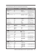
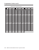
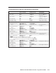
Using the Command/Response Tables
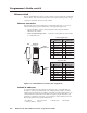
The command/response tables begin on page 4-8. Lower-case letters are acceptable
in the command field except where indicated for the gain and attenuation
commands. The table below shows the hexadecimal equivalent of each ASCII
character used in the command/response table.
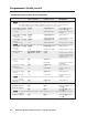
ASCII to HEX Conversion Table
Space
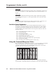
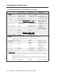
Symbols are used throughout the table to represent variables in the command/
response fields. Command and response examples are shown throughout the table.