User Guide Audio Products: Mixers and Processors MVC 121 Plus Three Input Stereo Mixer with DSP 68-1937-01 Rev.
Safety Instructions • English Warning This symbol is intended to alert the user of important operating and maintenance (servicing) instructions in the literature provided with the equipment. Power sources • This equipment should be operated only from the power source indicated on the product. This equipment is intended to be used with a main power system with a grounded (neutral) conductor. The third (grounding) pin is a safety feature, do not attempt to bypass or disable it.
FCC Class A Notice This equipment has been tested and found to comply with the limits for a Class A digital device, pursuant to part 15 of the FCC Rules. Operation is subject to the following two conditions: 1. This device may not cause harmful interference. 2. This device must accept any interference received, including interference that may cause undesired operation.
Conventions Used in this Guide In this user guide, the following are used: NOTE: A note draws attention to important information. TIP: A tip provides a suggestion to make working with the application easier. CAUTION: WARNING: A caution indicates a potential hazard to equipment or data. A warning warns of things or actions that might cause injury, death, or other severe consequences.
Contents Introduction ...................................................... 1 About This Guide................................................. 1 MVC 121 Plus Description................................... 1 MVC 121 Plus Features........................................ 2 MVC 121 Plus Application Diagram..................... 3 Rear Panel Features.............................................. 4 Front Panel Features............................................. 8 Operation......................................
MVC 121 Plus • Contents vi
Introduction This section describes this manual and the MVC 121 Plus, including: • About This Guide • MVC 121 Plus Description • MVC 121 Plus Features • MVC 121 Plus Application Diagram About This Guide This guide contains information about the Extron MVC 121 Plus audio mixer and volume controller with DSP. Unless otherwise specified, references in this guide to the “mixer” or “MVC” relate to the features or operation of the MVC 121 Plus.
MVC 121 Plus Features Emulate and live modes for configuration — The DSP Configurator control program can be used in emulate mode to create an MVC 121 Plus configuration offline. The modifications can be saved and applied to the unit when a connection is established. In live mode, the changes are made directly to the unit. Two mic/line inputs and one line level input — Two mic/line (mono, balanced or unbalanced) inputs can mix with one line level (stereo, balanced or unbalanced) input.
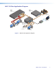
MVC 121 Plus Application Diagram Extron XPA 2001-70V Extron IN1508 Power Amplifier Scaling Presentation Switcher PU T 2 -23 OUT RS -70V A B L 01 A 20 XP NG R L 6 O DI 3 T PU 4 IN S2 5 8 AS R 2 C Y, Extron SI 26CT mA 50 TE /MU 10V VOL R F HP 1 80 Hz L(MO NO) DBY STAN Two-way Ceiling Speakers EL T L Y R PU IDEO 17TTIO/VTUS AUDARA LEV OFF US APP B RG RY, B- UT TP OU V 70 OTE REM S UT INP OUT ED LIST 1T23. U S I.T.E RI WI CL 7 AU C 0Hz , 50-6 1.
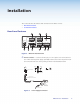
Installation This section describes the features and connectors for the MVC 121 Plus: • Rear Panel Features • Front Panel Features Rear Panel Features 4 L POWER 12V 0.4A MAX MIC +48V 5 INPUTS LINE 3 9 OUTPUTS MVC 121 Plus L VARIABLE R R RESET 1 MIC/LINE 2 L 1 FIXED R RS-232 DIGI IN 2 Tx Rx 1 Figure 2. a 2 3 6 1 2 3 8 7 MVC 121 Plus Rear Panel Power connector — Connect the two pole, 3.
CAUTION: Always use a power supply supplied or specified by Extron. Use of an unauthorized power supply voids all regulatory compliance certification and may cause damage to the supply and the end product. Unless otherwise stated, the AC/DC adapters are not suitable for use in air handling spaces or in wall cavities.
d Line input 3, left (L) and right (R) — A line level audio source, such as a CD player, MAIN wiring.eps output from a switcher,MVC DVD121 player, or other audio device, may be connected to the 5-pole 3.5 mm captive screw connector. Line inputs provide gain settings to accommodate consumer and pro operating line level sources. Balanced or unbalanced stereo connections can be wired to this connector (see the following example diagram).
L VARIABLE R Sound System CSR 6 RCA Adapter Do not tin the wires! R Right Tip Ring Sleeve(s) Tip Ring Unbalanced Stereo Output CAUTION: f Left R Left L L Tip NO GROUND HERE. Sleeve(s) Tip NO GROUND HERE. Right Balanced Stereo Output Connect the sleeve to ground. Connecting the sleeve to a negative (–) terminal will damage the audio output circuits. Fixed output left (L) and right (R) — The balanced/unbalanced stereo output from the 5-pole 3.
Both the RS-232 and the digital input connectors may be used simultaneously by using a 6-pin captive screw connector with two wires sharing the same ground connector (see the diagram below). RS-232 Tx Rx 2 DIGI IN 1 3 i Reset — The recessed reset button is used to access various modes of resets. The green power LED on the front panel indicates what mode of reset was accessed (see the MVC 121 Plus Hardware Reset Modes section for additional details).
e Line level 3 gain control — Rotating the encoder screw clockwise increases the gain setting, rotating the encoder screw counterclockwise decreases the gain setting. This adjustment controls the single gain point in the mix matrix that mixes stereo line level input 3 to the stereo output bus. The gain adjustment is indicated by the LED indicator bar (f). When the encoder screw rotation has stopped for three seconds or longer, the LED indicator returns to the output meter indication.
g Volume level adjust knob — Rotating the adjustment knob clockwise increases the output volume, rotating the knob counterclockwise decreases the volume. The LEDs light from bottom up as the volume level increases. VOLUME MVC 121 Plus MIXER/VOLUME CONTROLLER Use the rotary encoder to adjust the output volume from 0 (-100 dB) to 100% (0 dB). The default setting is 100% (0 dB).
Operation This section describes the operation of the MVC 121 Plus, including: • MVC 121 Plus Operation • DSP Processing/Signal Flow • Filter Processor Block • Mic/Line Input Signal Chain • Mixer • Output Channels MVC 121 Plus Operation The MVC 121 Plus can be configured using a PC running Windows XP or better and the DSP Configurator software (available on the included disc or at www.extron.com), or the Extron SIS Simple Instruction Set using HyperTerminal or DataViewer.
Front Panel Operation VOLUME MIX 1 2 3 MIC MIC LINE CONFIG MVC 121 Plus MIXER/VOLUME CONTROLLER 1 2 3 4 5 7 6 Figure 5. MVC 121 Plus Front Panel a Power/Reset LED — Green power indicator lights solid when the MVC is operational. The LED will blink when the reset button is pressed. b Configuration connector — The USB 2.0 port uses a mini type-B connector to connect to a host computer for control.
Power Cycle Current mixing and audio processor settings, the current state of the device, are saved in nonvolatile memory. When the unit is powered off, all settings are retained. When the unit is powered back on, it recalls settings from the nonvolatile memory. If a configuration was in process during the power down, these saved mix, audio level, and audio DSP processor settings become active. On power up the front power indicator LED lights solid when the unit is available for operation or programming.
Digital Input Port The three-pin digital input port (Digi In) is used to monitor or drive TTL level digital signals. The port consists of three input pins with the fourth pin being used as a ground providing three inputs total. The DSP Configurator software provides a selection of functions from a list, to be loaded to the MVC 121 Plus. NOTE: The digital input connectors are used to mute or unmute the input signal using a contact closure device.
3. Select the event or ‘trigger’ to configure the input. 4. The fixed functionality of the digital input is set to Mute/Unmute by default. 5. The fixed target mix-point is set to the selected digital input by default. 6. Select Apply to accept the changes.
DSP Processing and Signal Flow The diagram below shows the input signal flow and DSP processing per signal chain. Signal chains and mix-points are described in the following sections. 4 All signal routing, processing, and level control (gain/volume), are accomplished using software control from a PC connected to the MVC 121 Plus via the USB configuration port or the RS-232 port. The DSP Configurator program provides complete control while the SIS commands provide more limited control.
Fader Handle Signal Level Clicking the fader handle or clicking within the fader area brings focus to the fader. The input signal level can be adjusted using any of the following methods: • • Direct adjustment. Click and hold the fader handle, then drag it to the desired level in 0.1 dB steps. • Click or tab to the fader handle, then or to the desired level in 1 dB steps. Page Up and Page Down increases or decreases level in 10 dB steps.
Filter Processor Block A filter block can be configured for each MVC input. The following functions are available: • Insert — The filter block is inserted and made active by right-clicking on the block and selecting from the context menu or by double-clicking and entering selections. • Remove a filter — An active filter can be removed by right‑clicking on the block and selecting Delete or by selecting the block and pressing on the keyboard.
Figure 7. Filter Block Dialog Box Additional filters are inserted by opening the filter block dialog box, then selecting a filter type from the drop-down filter selection list. All filter parameters are modified via the Filter block dialog box. Each filter loads with all applicable default parameters displayed to the right of each drop-down filter selection list. Figure 8.
Note how filter 3 in the figure below is highlighted in yellow, indicating it is the filter in focus. The results of the filter in focus (independent of other filters) will show in the graph as a dotted line the same color as its filter row when bypassed. When active (not bypassed), the line is solid. Figure 9.
To demonstrate how Q affects the filter, see the following filter block below containing three parametric filters centered at different frequencies but with the same Q of 1.0. The filter in focus (b) has a center frequency of 1000 Hz boosting that frequency +12 dB over a Q of 1.0. Note the markers on either side of the peak frequency are at 200 Hz on the left and 5000 Hz on the right, a bandwidth of about 4800 Hz. Figure 10.
Low Pass The low pass filter is the opposite of the High Pass filter. All frequencies above the specified frequency are attenuated allowing lower frequencies to pass. Figure 12. Low Pass Filter Response Curve Here, the frequencies higher than the specified frequency, 10 kHz, are attenuated leaving the lower frequency response flat. Bass and Treble Shelving Bass and treble shelving may be added to the filter. Adding this filter automatically inserts both a bass and treble control row in the dialog box.
Mixer The DSP architecture contains a mixer that connects the mic/line and line inputs to the line outputs. The DSP Configurator GUI provides control of the mixer, used to set mix levels from the post processing inputs to the stereo line output bus. Each of the inputs is connected to a mix‑point and output to the stereo output bus.
Mix-point GUI behavior No mix information — A faint gray ball behind the mix-point indicates it is muted (contains no mix information). Mix information — A solid teal-colored “bubble” indicates the mix‑point is unmuted. Mouse-over — The cursor changes to a hand when a mouse‑over occurs at a mix‑point whether the mix-point contains mix information or not. Single-click — A single click brings focus, indicated by a dark green circle around either the ball or bubble, depending on mix status.
Mute — Muting or unmuting the left or right mute boxes of the mix-point dialog box will mute or unmute the corresponding output channel (L or R) as shown below. The corresponding half of the teal mix point ball will either be shaded (unmuted) or unshaded (muted).
In the example below, input audio from Mic/Line Input #1 is processed then arrives at the mix-point and is routed to the stereo output bus. Figure 15. Input 1 to Mix-point A double-click on the mix-point opens the dialog box, as shown on the right of the above diagram.
Double‑click on the Gain control block to adjust the fixed output from -24 dB to +12 dB with a step resolution of 0.1 dB, as shown below. In the following example, audio from the three inputs is processed individually and arrive at their separate mix-points. When the individual mix‑point mute buttons are released, the mix-point junctions turn teal to indicate the routing, and all three signals are routed to the Output, both variable and fixed.
Output Channels There are two stereo Outputs, as shown below. A Volume control block adjusts the Variable L/R output and a gain control block adjusts the fixed L/R outputs. Double‑click on the Volume control block to adjust the variable output. Double‑click on the Gain control block to adjust the fixed output. Volume The Volume control block monitors and adjusts the variable output from 0 dB to -100 dB with a step resolution of 1 dB. The meters monitor the output level.
SIS Programming and Control This section describes SIS programming and control of the MVC 121 Plus, including: • Connection Options • Command/Response Table for Basic SIS Commands • Command/Response Tables for DSP SIS Commands Connection Options The MVC 121 Plus can be remotely connected via a host computer or other device (such as a control system) attached to the rear panel RS‑232 port, or the front panel USB Config port.
USB Port (Front Panel) The MVC 121 Plus has a front panel USB port that can be connected to a host device such as a computer running the HyperTerminal utility, or the DataViewer utility. The port makes serial control of the switcher possible. Once the connection is established, see Using the Command/Response Tables below for SIS programming details. MVC 121 Plus-initiated Messages The MVC initiates messages under specific conditions. No response is required from the host.
Error Responses When the MVC 121 Plus is unable to execute the command, it returns an error response to the host. The error response codes and their descriptions are as follows: Code Description E01 Invalid input number E10 Invalid command E13 Invalid value (out of range) E14 Not valid for this configuration E23 Firmware update failure Although the MVC uses the same structure for SIS commands, there are two variations.
X1! = Input selection 1 = Mic 1 2 = Mic 2 3 = Line 3 X1@ = Output selection 1 = Variable 2 = Fixed X1# X1$ X2@ X2$ = Version number Listed to two decimal places (for example, x.xx) = Version and Build number The least significant bits is the build number (for example, x.xx.
Command/Response Table for Basic MVC 121 Plus SIS commands Command NOTE: ASCII Command (Host to Tuner) Response (Tuner to Host) Additional Description Commands can be entered back-to-back in a string, with no spaces. Example: TvprS25*11•3 Upper and lower case may be used interchangeably.
Command Read output name ASCII Command Response Additional Description (Host to Tuner) (Tuner to Host) E X1@ NO } Vrb mode 0/1: name ] Vrb mode 2/3: Nmo X1@ , name ] Read output name.
Digital Input Commands Command Configure digital input View digital input ASCII Command Response Additional Description E X! * X@ GPIT } E X! GPIT } Gpit X! * X@ ] X@* ] Gpit X! * X@ ] X% ] Sio X! * X% ] Tagged response Tagged response (Host to Tuner) (Vrb mode 2/3:) View I/O state X! ] Vrb mode 2/3: (Tuner to Host) X! X@ = Digital inputs, 1–3 Inputs 1–3 = Type of change to monitor 0 = Off (default) 1 = Edge, Hi to Lo 2 = Edge, Lo to Hi X% = State 0 = Logic Hi (inactive) 1 = Logic Lo (a
Command/Response Tables for DSP SIS Commands Digital signal processor (DSP) functions, gain and mute, can be controlled using SIS commands. These commands follow the same general rules as basic SIS commands, but the variables (X/) tend to be more complex. Also, a comprehensive understanding of the audio signal flow is helpful to understanding the commands. The following diagram shows the specific DSP processors available for SIS commands.
Error responses When the MVC 121 Plus is unable to execute the command, it returns an error response to the host.
Command/Response Table for MVC 121 Plus DSP SIS commands Command ASCII Command (Host to Tuner) Response (Tuner to Host) Additional Description NOTE: The command format is the same regardless of the control or mix-point selection. The acceptable adjustment range varies depending on the control or mix-point: • The mic/line input gain range is -18 dB to +60 dB (-180 to 600), in 0.1 dB increments. • The line input gain range is -18 dB to +24 dB (-180 to 240), in 0.1 dB increments.
Table 1.
Software Control This section describes the control software for the MVC 121 Plus, including: • Software Control • Windows-based Program Control • DSP Configurator Program Software Control The MVC 121 Plus can be controlled using the DSP Configurator software, SIS commands through HyperTerminal or DataViewer. The MVC has the following connection options: • RS-232 — One single stack 6-pole, 3.5 mm captive screw connector is used for bidirectional RS-232 (±5 V) serial control.
Figure 19. DVD Software Menu 3. Scroll to the DSP Configurator program and click the Install text to its right, as shown in the red boxes below. Figure 20. DVD Control Software Menu 4. Follow the on-screen instructions. By default, the Windows installation creates a C:\Program Files\Extron\DSP_Configurator folder for the DSP Configurator program files. 5. When the DSP Configurator installation is complete, the USB Installer starts automatically.
Install the USB Driver To install the USB driver, follow these instructions. Figure 21. USB Installer Splash Screen 1. After the DSP Configurator program installation is complete, click Next to proceed. Figure 22.
2. The USB driver installer is launched. When the installer has completed the installation of the USB drivers, the following screen appears: Figure 23. Successful USB Driver Installation 3. Click Finish. USB driver installation is complete. DSP Configurator Program Starting the Program 1. To run the DSP Configurator Program, click Start > Programs > Extron Electronics > DSP Configurator > DSP Configurator. The DSP Configurator program starts in Emulate mode (see to Emulate Mode vs. Live Mode).
2. Select the device to be configured and then click OK. . 3. The program displays the following screen. Using the Program In the DSP Configurator window Emulate mode, audio parameters may be selected, then transferred to the MVC by going to Live mode (while connected to the MVC 121 Plus). Audio settings can also be tailored while connected to the MVC which allows real-time auditioning of the audio output as adjustments are made.
Emulate Mode vs. Live Mode The DSP Configurator program has two operational modes: Live and Emulate. In live mode, the program has established a connection and is synced with the MVC 121. Changes affect the device in real-time and changes in the current state of the device are reflected in the DSP Configurator. In contrast, emulate mode allows the user to work offline, creating or editing configurations that do not immediately affect MVC 121 operation.
Selecting Live Mode and Pushing or Pulling a Configuration To switch from emulate mode to live mode: 1. Click the Mode Live button (see item a below). The Connect to device dialog box opens. 1 2 2 3a 3b or 3c MVC 121 Plus 4a 4b Figure 25. Selecting Live Mode 2. If necessary and as desired, click either the: • RS-232 tab (for connection to the rear panel RS-232 ports — proceed to step 3). • USB tab (for connection via the front panel configuration port — proceed to step 4). 3.
5a -or5b 6 6 7 8 Figure 26. Selecting Live Mode, continued 6. Click OK. The program prompts to save the current configuration. • If Pull is selected, the program updates the currently open file with the configuration from the device. Proceed to step 7. • If Push is selected, the program overwrites the device configuration with the currently open file. Proceed to step 8. NOTE: In either case, the program and device configuration will now reflect DSP Configurator changes in real-time.
7. Click OK. The DSP Configurator program updates the current configuration with the configuration from the MVC 121 and is now connected live. Changes to the configuration will be reflected immediately in the device operation. 8. Click OK. The DSP Configurator program uploads the current file created or opened in Emulate mode to the MVC 121. The file overwrites the configuration of the device, and DSP Configurator is now connected live.
Reference Information This section contains reference information for the MVC 121 Plus, including: • Specifications • Part Numbers and Accessories • Mounting • Firmware Loader • MVC 121 Plus Hardware Reset Modes Specifications Audio Gain ����������������������������������������������� Frequency response ������������������������ THD + Noise ����������������������������������� S/N ������������������������������������������������� Crosstalk ���������������������������������������� CMRR ��������������
Audio processing D/A conversion ������������������������������� 24 bit, 48 kHz sampling Audio output Number/signal type ������������������������ Connectors ������������������������������������ Impedance ������������������������������������� Gain error �������������������������������������� Maximum level (Hi-Z) ���������������������� 2 stereo, line, balanced/unbalanced (2) 3.5 mm captive screw connector, 5 pole 50 ohms unbalanced, 100 ohms balanced ±0.
Product weight ������������������������������� Shipping weight ����������������������������� Vibration ���������������������������������������� Regulatory compliance Safety �������������������������������������� EMI/EMC ��������������������������������� MTBF ��������������������������������������������� Warranty ���������������������������������������� 0.6 lbs (0.
Mounting The 1U high, quarter rack width, 3-inch deep MVC 121 Plus stereo mixer can be: • Set on a table, • Mounted on a rack shelf, • Mounted under a desk or tabletop, or • Mounted on a projector bracket. Tabletop Use Each MVC 121 Plus comes with rubber feet (not installed). For tabletop use, attach a self‑adhesive rubber foot to each corner of the bottom of the unit.
QuarterRackStandardShelf 1U Universal Rack Shelf 1/2 Rack Width Front False Faceplate 1/4 Rack Width Front False Faceplate Both front false faceplates use 2 screws. (2) 4-40 x 3/16" Screws Use 2 mounting holes on opposite corners. Figure 27. Mounting the MVC 121 Plus on a Universal Rack Shelf 3. Install blank panels or other units on the rack shelf.
QuarterRackUnderdeskMounting Figure 28. MBU 123, Under-Desk Mounting Firmware Loader The DSP Configurator program includes a firmware loader program which allows replacing the firmware without taking the MVC out of service. Download the desired firmware file from the Extron website, (see the Firmware Upgrade Page for instructions). To access the firmware uploader: 1. Select Tools, then Firmware Loader. 2. The Add Device dialog box appears. Type the IP address of the MVC, then press OK.
The Firmware Loader screen appears. 3. From the toolbar, select File > Open. 4. Locate the downloaded firmware file and click on it. 5. Click Begin on the main screen. The total progress bar tracks the loading progress. 6. When the upload is finished, exit the program by selecting File > Exit. The firmware upload is complete.
MVC 121 Plus Hardware Reset Modes MVC 121 Plus Reset Mode Summary Mode Mode Activation Use Factory Firmware 1 NOTE: After a mode 1 reset, update the MVC 121 Plus firmware to the latest version. DO NOT operate the firmware version that results from this mode reset. Purpose/Notes The MVC 121 Plus reverts to the factory default firmware. Event scripting does not start if the MVC 121 Plus is powered on in this mode. All user files and settings (drivers, adjustments, IP settings, etc.) are maintained.
Extron Warranty Extron Electronics warrants this product against defects in materials and workmanship for a period of three years from the date of purchase.