MVP 104GX Multi Video Processor 68-484-01 Printed in the USA
Precautions Safety Instructions • English This symbol is intended to alert the user of important operating and maintenance (servicing) instructions in the literature provided with the equipment. This symbol is intended to alert the user of the presence of uninsulated dangerous voltage within the product's enclosure that may present a risk of electric shock. Warning Power sources • This equipment should be operated only from the power source indicated on the product.
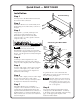
Quick Start — MVP 104GX Installation Rack mounting Step 1 Turn off power to the MVP 104GX and all other devices that will be connected. Step 2 IN 1 If the MVP 104GX is to be rack mounted, insert the mounting screws and washers, as shown on the right. PU TS 2 3 4 FR EE ZE AU DI PR O 1 2 3 4 ES ET S ST OR E AC TIVE AD FA PA CT TT OR ER Y NS 1 2 3 4 Step 3 JU ST MEN MEN TS U NE Using Inputs 1, 2, 3, and 4, attach up to four composite/S-video input devices to the MVP 104GX.
Quick Start — MVP 104GX, cont’d Menu Operation Default Cycle menu On power up of the MVP 104GX, a default cycle of two informational submenus displaying the product name and product type will appear in 2-second intervals. While in this cycle, all selected Input button LEDs will light green.
Table of Contents Chapter 1 • Introduction ................................................................................. 1-1 About the MVP 104GX ........................................................................................ 1-2 MVP 104GX Features ........................................................................................... 1-2 Chapter 2 • Installation ..........................................................................................................
Table of Contents, cont’d Blanking submenu ...................................................................................................... 3-11 Top submenu .............................................................................................................. 3-11 Bottom submenu ........................................................................................................ 3-11 Left submenu ...............................................................................................
MVP 104GX 1 Chapter One Introduction About the MVP 104GX MVP 104GX Features
Introduction About the MVP 104GX Extron’s MVP 104GX is a multi video processor featuring four inputs, three outputs, audio switching, and genlock capability. The MVP 104GX accepts up to four video inputs, both composite and S-video, and can simultaneously output all four video sources to a single output device. Each of the three outputs can display up to four discrete, scalable windows, one for every input source.
MVP 104GX 2 Chapter Two Installation Rack Mounting Procedure Rear Panel Connectors Connecting the MVP 104GX Setting Up Genlock and Vertical Interval Switching MVP 104GX Introduction
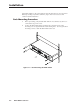
Installation If the MVP 104GX is to be rack mounted, follow the Rack Mounting Procedure below before proceeding any further. Otherwise, skip to Rear Panel Connectors and continue with the installation. Rack Mounting Procedure 1. Before proceeding, verify that the MVP 104GX is not cabled to any devices or connected to any power source. 2. Position the MVP 104GX in the mounting rack so that the 4 slots in the mounting ears are aligned with the rack mounting holes.
Rear Panel Connectors 14 13 GENLOCK INPUT 1 INPUT 2 IN IN OUT OUT INPUT 3 INPUT 4 IN OUTPUT IN IN A OUT OUT B L 1 R L INPUTS 2 R L 3 R L 4 R OUTPUT L 1 R OUT RS-232/RS-422 C REMOTE 100-240V 50/60 Hz 0.5A 2 1 3 4 5 6 7 8 9 10 11 12 Figure 2-2 — Rear panel of MVP 104GX 1 AC power — Standard AC power connector for a power source of 100 – 240VAC, operating at 50/60 Hz.
Installation, cont’d 13 Genlock input — Connect an external black burst signal for genlocking the video signal in broadcast or other sync-critical applications. 14 Genlock output — Connect any downstream equipment that requires genlocking for broadcast or other sync-critical applications. Connecting the MVP 104GX The MVP 104GX can be connected to as many as four input devices simultaneously and output to as many as three devices simultaneously.
4 Connect up to three output devices to the MVP 104GX using composite video output A, composite video output B, and S-video output C. 5 For stereo audio input, connect up to four audio sources to audio inputs 1, 2, 3, and 4. See the following Audio input and output section. 6 For stereo audio output, connect an audio output device to the 3.5 mm stereo audio output connector. See the following Audio input and output section.
Installation, cont’d Balanced audio 1. Attach the audio cable to a balanced speaker input connector (tip, ring, and sleeve), as shown here. Tip (+) Sleeve Ring (-) Tip (+) Sleeve (ground) 2. Attach the other end of the audio cable to the audio cable connector (Extron part number 10-319-10). Fasten the captive screws inside the audio cable connector as shown in figure 2-4. Balanced Audio Tip Ring Sleeve (s) Tip Ring Connect the sleeve(s) to ground (GND).
Genlock connections A genlock (black burst generator) device can be connected to the MVP 104GX via the BNC connectors shown below. The genlock feature allows the MVP 104GX to be synchronized with other system components for seamless vertical interval switching between sources. See Setting Up Genlock and Vertical Interval Switching in this chapter.
Installation, cont’d To synchronize the MVP 104GX’s video output with a genlock signal, follow these steps: 1. Power up and turn on all the devices that will use the genlock signal. The devices must be on for at least 15 to 20 minutes before proceeding with any adjustments. 2. Connect the active timing source signal to the Genlock In connector on the rear panel.
Oscilloscope displays What you see on the oscilloscope while adjusting the MVP 104GX to match the genlock signal depends on the type of signal used, the type of oscilloscope, and the procedure the scope requires. This section shows some examples of oscilloscope displays. Figure 2-6 below shows the genlock input signal (top) and an out-of-alignment NTSC composite sync output signal (bottom) displayed on a waveform monitor to check for alignment.
Installation, cont’d Figure 2-8 below shows an example of a view of a vectorscope during adjustment of the color subcarrier phase (SC/H). The subcarrier phase should be aligned to 0º (indicated in the figure by the triangle).
MVP 104GX 3 Chapter Three Operation Front Panel Features Menu Flowchart Front Panel Operation Optimizing the Image Using the Menu System MVP 104GX Installation
Operation Front Panel Features 13 PRESETS INPUTS 14 ADJUSTMENTS STORE 1 2 3 4 FREEZE ACTIVE AUDIO 1 2 3 4 1 2 3 4 FACTORY PATTERNS MENU NEXT ADJUST MVP 104GX MULTI VIDEO PROCESSOR 1 2 3 4 5 6 7 8 9 10 11 12 Figure 3-1 — Front panel details of the MVP 104GX 3-2 1 Input selection — The four input buttons turn on and turn off the input window images to the output. The green LED above each button lights whenever the input image is selected.
11 Vertical sizing — While the menu system’s LCD display is in the default mode (see the Menu Flowchart section) and a window is active, rotating this adjustment knob increases or decreases the vertical sizing of the window image. This knob is also used to adjust other functions.
Operation, cont’d Front Panel Operation PRESETS INPUTS ADJUSTMENTS STORE 1 2 3 4 FREEZE AUDIO ACTIVE 1 2 3 4 1 2 3 4 FACTORY PATTERNS MENU NEXT ADJUST MVP 104GX MULTI VIDEO PROCESSOR Figure 3-3 — MVP 104GX front panel The functions of the front panel controls are described in the following sections.
User presets Before storing any presets, first optimize the window images by setting the picture controls (contrast, brightness, tint, color), the sizing and positioning (horizontal and vertical), and the blanking (top, bottom, left, right). See the “Optimizing the Image” section. The eight user Preset buttons save/recall eight preset user-defined window output configurations, including window positioning, sizing, blanking, priority, test, and audio input selection.
Operation, cont’d 01 Input 1 Input 2 Input 3 Input 4 Input 1 Input 2 Input 2 Input 1 Input 1 05 Input 4 04 Input 3 Input 1 08 Input 3 Input 4 Input 2 Input 3 Input 2 Input 4 Input 2 Input 1 Input 2 09 Input 1 Input 2 Input 3 Input 2 12 Input 4 Input 1 Input 2 Input 1 Input 1 16 Input 1 Input 3 Input 2 Input 2 Input 3 Input 4 Input 2 Input 2 17 Input 1 Input 4 Input 3 13 Input 1 Input 3 Input 3 Input 3 Input 1 Input 4 Input 1 Input 4 Input 3 Input 2 Inp
displays the selected menus and submenus. See the sections Menu Flowchart and Using the Menu System. Horizontal sizing While the MVP 104GX is in the Default Cycle menu (see the Default Cycle menu section), selecting an active input window and rotating the Horizontal sizing knob sizes the selected window image horizontally. See the Position/Size window menu section.
Operation, cont’d in mind that sizing the window horizontally moves the right side of the window only. b. Horizontal sizing — Rotate the Horizontal sizing knob to adjust the right side of the window. Vertical positioning — Rotate the Vertical positioning knob to move the top side of the selected window to a desired location, keeping in mind that sizing the window vertically moves the bottom side of the window only. c. d. 3.
Using the Menu System The MVP 104GX menu system is accessed through the Menu and Next buttons while viewing the LCD panel display. See the previous Menu Flowchart section as a helpful guide while navigating the menu system. Use the chart below to reference the various flowchart arrows.
Operation, cont’d Vertical sizing: Horizontal sizing: Vertical positioning: Horizontal positioning: Press the Menu button to advance to the Picture Controls menu, or return to the Default Cycle menu by allowing the 16-second time-out to occur. Picture Controls menu The Picture Controls menu adjusts the contrast, brightness, tint, and color of a selected window image by rotating the Vertical sizing knob. The picture control settings are displayed on the bottom of the LCD panel.
corner of the LCD panel. Press the Next button to return to the Picture Controls menu, or press the Menu button to exit the Color submenu and advance to the Window Blanking menu. Window Blanking menu ACTIVE 1 2 3 4 Remove unwanted information/noise from the edges of each displayed image by adjusting the blanking.
Operation, cont’d Right submenu Increase or decrease the Right blanking from 0 to 16 by rotating the Vertical sizing knob until the unwanted information no longer appears. The selected window number (1, 2, 3, or 4), designated by pressing the Active window selection button, is displayed in the upper right corner of the LCD panel. Press the Next button to return to the Window Blanking menu, or press the Menu button to exit the Right submenu and advance to the Audio Configuration menu.
Window Priority submenu The priority of each window determines if a window is displayed in front (priority A) or further back (priorities B, C and D, with D being furthest back). While this submenu is active, all Input button LEDs blink green. Change the priority (A, B, C, or D, with A being the highest [top] priority and D being the lowest [bottom] priority) of all 4 output windows (1, 2, 3, 4) by rotating the Vertical sizing knob to select the window.
Operation, cont’d Text Style submenu Specify the text style for all output windows as either solid or translucent by rotating the Vertical sizing knob. Press the Next button to advance to the Text Location submenu, or press the Menu button to exit the Text Style submenu and proceed to the Genlock menu. Text Location submenu Specify the text location for all output windows by rotating the Vertical sizing knob and selecting top left, top center, top right, bottom left, bottom center, or bottom right.
Confirm Reset submenu Confirm the menu system reset by first holding down the Freeze button, then press the Next button (the system advances to the System Resetting Please Wait submenu), or press the Next button to return to the Background Color submenu, or press the Menu button to exit the Confirm Reset submenu and proceed to the Genlock menu. System Resetting Please Wait submenu After 2 seconds, the menu system defaults to the Default Cycle menu.
Operation, cont’d 3-16 MVP 104GX Operation
MVP 104GX 4 Chapter Four Windows®-based Control Program Installing Windows-based Control Software Using the Software MVP 104 Operation
Windows-based Control Program The MVP and SVS Control Program (Extron part number 29-047-01), which is used by the MVP 104GX, requires Windows 95/98, NT, or later. It provides remote control of MVP 104GX functions. Installing the Windows®-based Control Software The program is contained on two 3.5-inch diskettes. The program occupies approximately 1.5 MB (megabytes) of hard-drive space. Run the program from the hard drive. To install the software from the floppy disks onto the hard drive, run SETUP.
3. Using normal Windows controls, you can perform many of the same adjustments as from the MVP 104GX front panel. The illustration below, which shows the four input windows, is an example of the window adjustment screen that appears after the Adjust Window button is selected from the previous MVP and SVS Control Program main screen. The window sizes, position, priorities, text, text placement, blanking around images, and background colors can be adjusted from this window.
Windows-based Control Program, cont’d 4-4 MVP 104GX Windows-based Control Program
MVP 104GX 5 Chapter Five Programmer’s Guide Remote Control Port (RS-232/RS-422) Host-to-MVP 104GX Communications MVP 104 Windows Control Program
Programmer’s Guide Remote Control Port (RS-232/RS-422) The MVP 104GX RS-232/RS-422 port connector is used to connect to a host or external controlling device, such as a computer or control system which can generate the proper command codes and recognize the MVP 104GX responses. 5 1 RS-232/RS-422 REMOTE 9 6 DB9 Pin Locations Female The MVP 104GX comes from the factory configured for RS-232. To set the MVP 104GX for RS-422 operation, see “Configuring the MVP 104GX for RS-422” in the appendix.
The copyright message is initiated by the MVP 104GX when it is first powered on. Vx.xx is the firmware version number. RECONFIG The Reconfig message is initiated by the MVP 104GX when a local event takes place, such as a front panel operation. The MVP responds by sending an unsolicited response (Reconfig##) to the Host. See MVP 104GX-generated unsolicited responses at the end of the command/response table. Using the command/response table The command/response table is shown on the following pages.
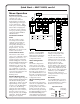
Programmer’s Guide, cont’d ASCII to HEX Conversion Table • Figure 5-1 — ASCII-to-hexadecimal conversion table COMMAND/RESPONSE TABLE COMMAND Horizontal Shift Shift right Shift left ASCII RESPONSE DESCRIPTION +H –H Hph Hph Shift input Shift input image right one step image left one step +/ –/ Vph Vph Shift input Shift input image down one step image up one step +: –: Hsz Hsz Increase input Decrease input horizontal size one step horizontal size one step +; –; Vsz Vsz Increase input Decre
COMMAND Contrast ASCII Specific value Increment up Decrement down RESPONSE DESCRIPTION * ^ +^ –^ Con Con Con Sets input contrast to Increment input contrast one step Decrement input contrast one step * Y +Y –Y Brt Brt Brt Sets input brightness to Increment input brightness one step Decrement input brightness one step * C +C –C Col Col Col Sets input color to Increment input color one step Decrement input color one step * T +T –T Tin Tin Tin Sets input tint to Increment input tint one step De
Programmer’s Guide, cont’d COMMAND ASCII Audio Channel Gain Audio gain * RESPONSE DESCRIPTION G In •Aud= Set audio gain for input to g In •Aud= Set audio attenuation for input G g In In •Aud= •Aud= Display audio gain for input Display audio gain for input . Rpr Recall user preset , Spr Save user preset .
COMMAND ASCII Request Information General RESPONSE I/i Current picture control A •Aud •Pri •TpA j •TpB j •Tlc I T h •Aud •Kro •[ Current windowing i User preset picture control * User preset windowing * i Hph Factory pattern picture control * I T h •Aud •Kro •[ Factory pattern windowing * General user presets *0I General factory patterns Hph I i *0I •Hsz T h •Aud •Kro •[ Hph f f •Hsz f •Hsz •Col ] •Tin •Vph •Col ] •Con •Vsz • Tin •Vph •Col ] •Bdr •Blt •Con •Vsz •Tin
Programmer’s Guide, cont’d T2•Aud+02•Col100•Tin22•Con95•Brt20•Frz0•Blk0•Det1 •Kro1•[FEW WORDS] The following response example refers to input 2. Video type detected (T) = 2 (PAL) Audio gain (Aud) = +02dB Picture color (Col) = 100 Picture tint (Tin) = 22 Picture contrast (Con) = 95 Picture brightness (Brt) = 20 Freeze window (Frz) = 0 (off, i.e. image not frozen) Window blanking (Blk) = 0 (blanking off, i.e.
MVP 104GX A Appendix Reference Information Configuring the MVP 104GX for RS-422 Specifications MVP 104 Programmer’s Guide
Reference Information Configuring the MVP 104GX for RS-422 The MVP 104GX comes configured from the factory for RS-232 communications. If an RS-422 configuration is required, follow the procedures below. The procedures involve removing the top cover, relocating the serial port ribbon cable, setting the jumper, and replacing the top cover. Removing the top cover The top cover of the MVP 104GX must first be removed to gain access to the ribbon cable and jumper. 1.
3 1 3 1 3 1 RS-232 RS-422 J23 IN OU T IN PU IN T1 OU T IN PU Ribbon Cable IN T2 IN PU IN OU T3 T IN PU OU T4 T A B OU TP UT C L 1 R L 2 INP U R TS L 3 R L 4 R OU T L PUT 1 R GE NL OC K IN RS -232 /422 RE MO TE OU T RS-422 Pin Connector RS-232 Pin Connector Figure A-2 — RS-232 to RS-422 cable and jumper positioning 3. Remove and replace the jumper on the alternate jumper position, as shown in figure A-2. Replacing the top cover 1.
Specifications — MVP 104GX Video input and loopout Number/signal type ................... 4 S-video, 8 NTSC/PAL composite video Connectors .................................... 4 4-pin mini-DIN female ....... S-video 8 BNC female ........................... composite video Nominal level ............................... 0.7V to 1.0V p-p Minimum/maximum level(s) .... 2.0V p-p Impedance .................................... 75 ohms or Hi Z Vertical frequency .......................
Audio output Number/signal type ................... Connectors .................................... Impedance .................................... Gain error ...................................... Drive (Hi-Z) .................................. Drive (600 ohm) ........................... 1 stereo, balanced/unbalanced 1 3.5 mm captive screw terminal, 5-pole 50 ohms, unbalanced; 100 ohms, balanced ±0.
A-6 MVP 104GX Reference Information
FCC Class A Notice Note: This equipment has been tested and found to comply with the limits for a Class A digital device, pursuant to part 15 of the FCC Rules. These limits are designed to provide reasonable protection against harmful interference when the equipment is operated in a commercial environment. This equipment generates, uses and can radiate radio frequency energy and, if not installed and used in accordance with the instruction manual, may cause harmful interference to radio communications.
Extron Electronics, USA 1230 South Lewis Street, Anaheim, CA 92805 800.633.9876 714.491.1500 FAX 714.491.1517 USA Extron Electronics, Europe Beeldschermweg 6C, 3821 AH Amersfoort +31.33.453.4040 FAX +31.33.453.4050 The Netherlands Extron Electronics, Asia 135 Joo Seng Rd. #04-01, PM Industrial Bldg. +65.383.4400 FAX +65.383.4664 Singapore 368363 Extron Electronics Information ExtronWEB™: www.extron.com ExtronFAX™: 714.491.