User Guide Twisted Pair MTPX Plus Series MTP Twisted Pair Matrix Switchers 68-1383-01 Rev.
Safety Instructions • English This symbol is intended to alert the user of important operating and maintenance (servicing) instructions in the literature provided with the equipment. This symbol is intended to alert the user of the presence of uninsulated dangerous voltage within the product’s enclosure that may present a risk of electric shock. Warning Power sources • This equipment should be operated only from the power source indicated on the product.
FCC Class A Notice This equipment has been tested and found to comply with the limits for a Class A digital device, pursuant to part 15 of the FCC Rules. Operation is subject to the following two conditions: This device may not cause harmful interference. 1. This device must accept any interference received, including interference that may cause undesired operation.
Conventions Used in this Guide In this user guide, the following are used: NOTE: A note draws attention to important information. TIP: A tip provides a suggestion to make working with the application easier. CAUTION: WARNING: A caution indicates a potential hazard to equipment or data. A warning warns of things or actions that might cause injury, death, or other severe consequences.
Contents Introduction............................................. 1 Mounting the Switcher................................... 11 Rear Panel Cabling and Settings...................... 11 Signal Inputs............................................... 12 RS-232 Output Inserts................................. 15 Signal Outputs............................................ 16 Remote Connection.................................... 18 Ethernet Connection................................... 19 Reset Button..............
Using Emulation Mode.............................. 119 Using the Help System.............................. 120 Optimizing the Video.................................... 121 MTP Transmitter Pre-Peak Selection........... 121 MTPX Level/Peaking Setting...................... 121 MTPX Skew Setting................................... 122 MTPX Plus Pre-Peak Selection.................... 123 MTP Receiver Level/Peaking Setting........... 123 Button-Label Generator Program..................
Introduction • About this Manual • About the Matrix Switchers • TP Cable Advantages • Features About this Manual This manual contains installation, configuration, and operating information for the Extron® MTPX Plus MTP Twisted Pair Matrix Switchers. About the Matrix Switchers The MTPX Plus matrix switchers distribute signals that are compatible with the Extron MTP and VTT/VTR product lines.
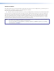
Rack Mounted PC Control System TCP/IP Network Extron MTP U R RSA SEQ Universal Receiver 2 -23 RS E AC SP UT S Rx Tx TP OU NO RS 232 DIO AU 2 MO 1 VID Y Audio B- Y/C Y Y R- B RG WER POV X 12 MA .
The switcher can be operated remotely by any of the following when that device is connected to either MTPX Plus serial port: • A control system • A PC • An Extron MKP 2000 remote control panel • An Extron MKP 3000 remote control panel For some outputs (most matrix sizes) or all outputs (MTPX Plus 128), bidirectional passthrough RS-232 signals from a dedicated source (rather than from the selected input) can be directly inserted into the signal set routed to the TP output.
TP Cable Advantages Twisted pair cable is much smaller, lighter, more flexible, and less expensive than coaxial cable. These TP products make cable runs simpler and less cumbersome. Termination of the cable with RJ-45 connectors is simple, quick, and economical. CAUTION: Do not connect this device to a computer data or telecommunications network.
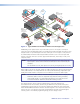
Table 1. 1 Recommended maximum TP transmission distances at 60 Hz, MTP transmitter to switcher when the display is on the MTPX Plus local (VGA) output MTP Transmitter MT P T 1 5 HD A AUDIO PRE-PEAK POWER 12V .
Table 2. Recommended maximum TP transmission distances at 60 Hz, — transmitter to receiver using MTPX Plus TP inputs and outputs MTP Transmitter 3 PRE-PEAK 12V .
Table 3. Recommended maximum TP transmission distances at 60 Hz, — VTT transmitter to VTR receiver using MTPX TP inputs and outputs VTT Transmitter 3 TX VTR Receiver LOCAL INPUTS 2 3 4 5 6 7 8 9 10 11 12 13 14 15 16 ® INPUT SELECT LOCAL 1 2 3 4 5 6 17 RJ-45 RS-232 OUTPUT INSERTION 1 Tx Rx 2 Tx Rx 3 Tx Rx 4 5 Tx Rx 6 Tx Rx 7 Tx Rx Tx Rx RX INPUTS 1 18 19 20 21 22 23 24 LOCAL OUTPUTS 8 25 26 27 28 29 30 31 US LISTED 1T23 I.T.E.
Skew equalization Skew exists between wire pairs when the physical length of one wire pair is different from another. Skew affects the displayed image when the differential length between wire pairs exceeds 2 feet. This causes the timing of the red, green, and blue video signals to appear out of alignment (horizontal registration errors). The signals transmitted on the shortest pair are shifted to the left if you are viewing white lines on a black background.
Switching flexibility — The switcher provides individually buffered, independent, matrix switched outputs with audio follow and audio breakaway. • Tie any input to any or all outputs. • Quick multiple tie — Multiple inputs can be switched to multiple outputs simultaneously. This allows all displays (outputs) to change from source to source at the same time. • Audio follow — Audio can be switched with its corresponding video input via front panel control or via serial port remote control.
Rack mounting — The 1U high (MTPX Plus 128), 2U high (other matrix sizes 1616 and smaller), or 3U high (matrix sizes 1632 and larger) enclosure is rack mountable in any conventional 19-inch wide wide rack. The 2U and 3U enclosures are mountable without extra hardware. The 1U enclosure is rack mountable using the provided mounting kit.
Installation This sections details the installation of the MTPX Plus Matrix Switchers, including: • Mounting the Switcher • Rear Panel Cabling and Settings • Front Panel Configuration Port Mounting the Switcher CAUTION: Installation and service must be performed by authorized personnel only. Detailed mounting instructions can be found in the “Reference Information“ section at the end of this guide.
Figure 4 shows the rear panel of the MTPX Plus 3232.
Figure 5 shows the recommended termination of TP cables in accordance with the TIA/EIA T568A or TIA/EIA T568B wiring standards. You can use either standard with CAT 5, 5e, or 6 cable, but use the same standard on both ends of the cable. Pins: 12345678 Pin Insert Twisted Pair Wires RJ-45 Connector Figure 5. NOTE: b T568A T568B Wire color Wire color Video input (via transmitter or local input) RGB Composite S-video 1 White-green White-orange Red+/V.
c Audio Inputs (local audio) connectors — Connect balanced or unbalanced stereo audio inputs to these 3.5 mm, 5-pole captive screw connectors. Connectors are included with each switcher, but you must supply the audio cable. See figure 7 to wire a connector for the appropriate input type and impedance level. Use the supplied tie-wrap to strap the audio cable to the extended tail of the connector. High impedance is generally over 800 ohms. Figure 7.
RS-232 Output Inserts e RS-232 Output Insert connectors — For bidirectional RS-232 data that is routed to a specific (unswitchable) TP output, connect a serial device to one of these 3.5 mm, 3-pole captive screw connectors. Figure 9 shows how to wire the connectors. Tx Rx RS-232 Device Do not tin the wires! Figure 9.
Signal Outputs f Outputs (MTP) connectors — Connect the TP inputs of compatible MTP or VTR receivers to these RJ-45 female connectors. See the Inputs connector (item a) in the “Signal inputs” section, for detailed pin assignments for the RJ-45 connectors. CAUTION: Do not connect this device to a computer data or telecommunications network. NOTE: g For best results, use a cable length of at least 25 feet (7.5 m) between the TP output connector and the receiver.
h Mono Audio (local audio) outputs — Connect audio devices, such as an audio amplifier or powered speakers, to these four or eight 3.5 mm, 5-pole captive screw connectors. These connectors output the selected unamplified, mono line level audio. See figure 10 to wire an output connector. Use the supplied tie-wrap to strap the audio cable to the extended tail of the connector. R Do not tin the wires! L Tip Ring Sleeve(s) Tip Ring Mono Output Figure 10.
Remote Connection Connect a host device, such as a computer, touch panel control, or RS-232 capable PDA to the switcher via the remote port of your switcher. NOTE: The port can operate at 9600, 19200, 38400, or 115200 baud rates. Models other than the MTPX Plus 128 can support either the RS-232 or RS-422 serial communication protocol (see “Selecting the Rear Panel Remote Port Protocol and Baud Rate” in the “Operation” section to configure the Remote port from the front panel).
Ethernet Connection NOTE: LAN port — If desired, for IP control of the switcher, connect the switcher to a PC or to an Ethernet LAN via this RJ-45 connector. You can use a PC to control the networked switcher with SIS commands from anywhere in the world. You can also control the switcher from a PC that is running the Extron Matrix Switchers Control Program or has downloaded HTML pages from the switcher.
Reset Button l Reset button — The Reset button initiates two levels of reset to the matrix switcher. For two different reset levels, press and hold the button while the switcher is running or while you power up the switcher. RESET See “Rear Panel Operations” in the “Operation” section for details. • Rear panel (mode 5) system reset — Press and hold the Reset button until the Reset LED blinks three times (approximately 9 seconds), then release the button and push it again.
6 feet (1.8 m) 1 Part #70-335-01 6 9 5 Tip Ring 9-pin D Connection TRS Plug Pin 2 Pin 3 Pin 5 Computer's RX line Computer's TX line Computer's signal ground Tip Ring Sleeve Sleeve (Gnd) Figure 15. Optional 9-pin TRS RS-232 cable NOTE: The stereo jack Configuration port (item o) protocol can be changed under SIS command control only (see the Set serial port parameters SIS Command, in the “Programming Guide” section to configure all ports under SIS control).
Operation This section describes the front panel operation of the MTPX Plus Matrix Switcher, including: • Front Panel Controls and Indicators • Front Panel Operations • Rear Panel Operations • Optimizing the Audio • Video Adjustments • Troubleshooting • Configuration Worksheets Front Panel Controls and Indicators The front panel controls (see figure 16 through figure 18) are grouped into two sets. The input and output buttons, a and b, are grouped on the left side of the control panel.
1 INPUTS 1 2 3 4 5 6 7 8 9 10 11 12 13 14 15 16 1 2 3 4 5 6 7 8 9 10 11 12 13 14 15 16 CONTROL CONFIG ENTER PRESET I/O VIEW ESC AUDIO VIDEO OUTPUTS MTPX PLUS SERIES MTP MATRIX SWITCHER 2 3 4 5 6 7 8 Figure 17.
Input and Output Buttons NOTE: See “Front Panel Operations” for detailed descriptions of the following operations. Primary functions Action Select input or output for tie being created. Indication Blink: potential tie/untie.
a b Input buttons — The input buttons have one primary function (❏) and six secondary functions (•): ❏ Select and identify an input. • (Input 1 only) With the Output 1 button, select I/O Group mode. • Assign an input to the selected group in I/O Group mode and indicate its assignment. • Select a preset. • Display the output volume level. • Select and identify the audio/RS-232 wire pair as audio (unlit) or RS-232 (lit) in Serial Port and Audio/RS-232 Input Configuration mode.
Control Buttons and LEDs NOTE: See “Front Panel Operations” for detailed descriptions of the following operations.
d e Preset button — The Preset button has two primary functions (❏) and three secondary functions (•): ❏ Activates Save Preset mode to save a configuration as a preset and Recall Preset mode to activate a previously-defined preset. ❏ Blinks when Save Preset mode is active and lights steadily when Recall Preset mode is active. • In the I/O Group mode, selects group 2 and indicates the selection. • With the Enter, View, and Esc buttons, selects Serial Port and Audio/RS-232 Input Configuration mode.
I/O Controls NOTE: See “Front Panel Operations” for detailed descriptions of the following operations. Primary functions Action Indication Select video Select audio Green: selected Red: selected VIDEO AUDIO Secondary functions Front panel locks Resets Action 1 With Enter, select Lock mode 2 or toggle between mode 0 and mode 2. Action 2 Select Lock mode 1 or toggle between mode 2 and mode 1. Action 1: Perform a system reset.
Button Icons The numbered translucent covers on the input and output pushbuttons can be removed and replaced to insert labels behind the covers. Input and output labels can be created easily with the Extron Button-Label Generator software, which is shipped with every Extron matrix switcher. Each input and output can be labeled with names, alphanumeric characters, or color bitmaps for easy and intuitive input and output selection (see figure 19).
Definitions The following Extron matrix switcher terms are used throughout this manual: Tie — An input-to-output connection Set of ties — An input tied to two or more outputs. NOTE: An output can never be tied to more than one input. Configuration — One or more ties or one or more sets of ties Current configuration — The configuration that is currently active in the switcher (also called configuration 0) Global memory preset — A configuration that has been stored.
Creating a Configuration The current configuration can be changed using the front panel buttons. Change the current configuration as follows: 1. Press the Esc button to clear any input button indicators, output button indicators, or control button indicators that may be lit. 2. Select video, audio, or both for configuration by pressing the Video button and Audio button as necessary. 3. Select the desired input and output(s) by pressing the input and output buttons.
Example 1: Create a set of video and audio ties 1. Clear all selections: Press and release the Esc button. Press the Esc button to clear all selections. C O NT R O L ENTER PRESET VIEW ESC The button flashes once. 2. Select video and audio for the tie: If necessary, press and release the the Video button and the Audio button to light both. I/O VIDEO AUDIO Press the Video button to toggle on and off. Press the Audio button to toggle on and off. The button lights green when selected.
The current configuration (see figure 20) is now: • Input 5 video and audio are tied to output 3, output 4, and output 8 Input 5 (video/audio) tied to outputs 3, 4, and 8 Input 5 3 4 Output 8 Video Audio Figure 20. Example 1, Final Configuration Example 2: Add a video tie to a set of video and audio ties In the following example, a new video tie is added to the current configuration. The example shows the front panel indications that result from your actions.
5. Confirm the change: Press and release the Enter button. Press the Enter button to confirm the configuration change. All input buttons and output buttons return to unlit or background illumination. ENTER The Enter button returns to unlit or background illumination. The current configuration (see figure 21) is now: • Video — Input 5 video is tied to output 1, output 3, output 4, and output 8. • Audio — Input 5 audio is tied to output 3, output 4, and output 8.
3. Select an input: Press and release the input 5 button. Press the button. The button lights red. 1 2 3 4 5 6 7 8 16 17 18 19 20 21 22 23 24 32 I N P U T S The Output 3, Output 4, and Output 8 buttons light red to indicate the audio ties created in example 1. 1 2 3 4 5 6 7 8 16 17 18 19 20 21 22 23 24 32 O U T P U T S The Output 1 button does not light to indicate the tie created in example 2 because that tie is video only. 4. Select the output: Press and release the output 4 button.
The current configuration (see figure 22) is now: • Video — Input 5 video is tied to output 1, output 3, output 4, and output 8. • Audio — Input 5 audio is tied to output 3 and output 8. Input 5 video tied to outputs 1, 3, 4, and 8 Input 5 audio tied to outputs 3 and 8 Input 5 1 3 4 Output 8 Video Audio Figure 22. Example 3, Final Configuration Viewing the Configuration The current configuration can be viewed using the front panel buttons.
Example 4: Viewing video and audio (RS-232), audio (RS-232) only, and video only ties In the following example, we view the video and audio (or RS-232), audio- (or RS-232) only, and video-only ties in the current configuration. The steps show the front panel indications that result from your action. NOTE: This example assumes that you have performed example 1, example 2, and example 3. 1. Clear all selections: Press and release the Esc button. 2. Select View-only mode: Press and release the View button.
NOTE: You can also view a set of ties by selecting a tied output. Demonstrate this as follows: • Note the number of a lit output button, and then press and release the output button for an untied (unlit or background illumination) output. • Observe that all of the untied outputs light. • Then press the output button that you noted previously • Observe that the selected output button, the tied input button (input 5), and the output buttons light for all of the outputs that are tied to the input. 5.
I/O Grouping I/O grouping is a matrix switcher feature that allows you to subdivide the front panel controls of the matrix into four smaller functional sub-switchers and limit tie creation using the front panel only. Inputs and outputs can be assigned to one of four groups or not assigned to any group. When you are creating ties on the front panel, inputs and outputs that are assigned to a group can be tied only to other outputs and inputs within the same group.
You can break audio away from the video for a given input or output (assign video and audio to different groups) by isolating only video or only audio using the front panel Video and Audio buttons after you select I/O Group mode (between steps 2 and 3, below). Audio breakaway across different groups can be confusing when you are operating the front panel.
Example 5: Grouping inputs and outputs In the following example, several switcher inputs and outputs are assigned to groups. The steps show the front panel indications that result from your action. 1. Clear all selections: Press and release the Esc button. 2. Enter I/O Group mode: Simultaneously press and hold the Input 1 and Output 1 buttons for approximately 2 seconds and then release the buttons. Release the Input 1 button and Output 1 button. • Ungrouped input and output buttons light.
b. Press and release the Output 1 through 4 buttons. Press the buttons. The selected buttons light green. 1 2 3 4 5 6 7 8 15 16 17 18 19 20 21 22 23 24 31 32 O U T P U T S 5. Select group 2: Press and release the Preset button. Press the button. The button lights amber to indicate the selection. C O NT R O L ENTER PRESET Group # 1 2 VIEW ESC 3 4 6. Assign inputs and outputs to group 2: a. Press and release the Input 5 through 8 buttons. Press and release the buttons.
Using Presets The current configuration (configuration 0) can be saved as a preset in any one of 32 preset memory addresses. All 32 presets are assigned to the input buttons and (where necessary) output buttons and are available to be either saved or retrieved from the front panel. Up to 20 (MTPX Plus 128) or all 32 (all other models) presets can be selected from the front panel to be either saved or retrieved. When a preset is retrieved from memory, it becomes the current configuration.
Example 6: Saving a preset In the following an example, the current configuration is saved as a preset. The example shows the front panel indications that result from your actions. 1. Clear all selections: Press and release the Esc button. 2. Select Save Preset mode: Press and hold the Preset button for approximately 2 seconds until it blinks. Preset Assigned Press and hold the Preset button until it blinks. PRESET 1 2 3 4 15 16 PRESET 2 seconds All input buttons with assigned presets light red.
Example 7: Recalling a preset In the following example, a preset is recalled to become the current configuration. The steps show the front panel indications that result from your action. 1. Clear all selections: Press and release the Esc button. 2. Select Recall Preset mode: Press and release the Preset button. Preset Assigned Press and release the Preset button. The Preset button lights. 1 2 3 15 16 PRESET All input buttons with assigned presets light red.
Muting and Unmuting Audio/RS-232 Outputs Individual audio or RS-232 outputs can be muted or unmuted as follows: NOTE: Output mutes are protected when front panel Lock mode 2 is selected. You can view the status of the output (muted or unmuted) in Lock mode 2 but you cannot change it from the front panel (see “Setting the Front Panel Locks (Executive Modes)” on page 59). 1. Press the Esc button to clear any input button indications, output button indications, or control button indications that may be on.
Example 8: Muting and unmuting an audio/RS-232 output In the following example, a switcher output is muted and unmuted. The steps show the front panel indications that result from your action. 1. Clear all selections: Press and release the Esc button. 2. Select View-only mode: Press and release the View button. The View button lights red. 3. Select audio (or RS-232) for viewing and muting: If necessary, press and release the Audio button.
Viewing and Adjusting the Input Audio Level The audio level of each input can be displayed and adjusted through a range of -18 dB to +24 dB to ensure that there is no noticeable volume difference among sources (see figure 25). The audio level can be adjusted from the front panel or under remote control. The default audio level is 0 dB.
NOTES: • Pressing the Enter or Preset button also exits Audio mode. Pressing the Preset button changes to Recall Preset mode. • There is one audio level setting per input. The audio level setting is shared by the left and right audio inputs. • The audio level settings are stored in non-volatile memory. When power is removed and restored, the audio level settings are retained.
Table 5.
Example 9: Viewing and adjusting an input audio level NOTE: This procedure can only be performed if the audio/RS-232 wire pair of the input is defined as audio (see ”Defining the Audio/RS-232 Wire Pair” on page 62).
Figure 28 shows the same +8 dB level as figure 26, but displayed on an 8-output-button MTPX Plus 128. 1 2 3F 4 5 6 7 8 Figure 28. Level Display on an 8-Output-Button Switcher 4. Change the audio level: Press and release the View (<) button once (see figure 29) to decrease the input audio level by 1 dB. Press and release the View (<) button several more times (see figure 29) to decrease the input audio level by 1 dB per button press.
Viewing and Adjusting the Local Output Volume The audio level of each local output can be displayed and adjusted through a range of 100% (no attenuation) to 0% (maximum [76 dB] attenuation). The audio level can be adjusted from the front panel or under serial port, USB port, or Ethernet control. The default volume is 100% (no attenuation). NOTE: Output volume is protected when front panel Lock mode 2 is selected.
Reading the displayed volume This section is a detailed look at reading the output volume display on the front panel. If you do not need to read the exact value of the volume setting, skip this section. There are 65 steps of volume attenuation, with 1 dB per step (button push), except for 0-to-1, which is 13 dB. At maximum attenuation, no input buttons are lit, 76 dB of attenuation is applied, and the audio output is effectively muted.
Table 6.
For example: When lit steadily, the Input 3 button indicates the following, depending on the number of input buttons the switcher has: • • Switchers with 12 input buttons — 47 dB of attenuation when compared to the Input 3 button blinking quickly (48 dB to 50 dB of attenuation). The blinking Input 4 button (45 dB to 46 dB of attenuation) is at least 2 dB less than the fast blinking Input 3 button (48 dB minus 46 dB) and at most 5 dB less (50 dB minus 45 dB).
3. Select an output: Press and release the output 1 button. In figure 32 through figure 34, the lit or blinking input buttons indicate 41.5 percent of the applied audio input. The unlit input buttons indicate an audio volume attenuation of 39 dB. Figure 33 and figure 34 show the same 41.5 percent, 39 dB volume. • 39 dB attenuation • 41.5% volume 1 Press the button.
4. Change the volume: Press and release the Esc (>) button once (see figure 35) to increase the volume by 1.5%. Press and release the Esc (>) button several more times (figure 3-57) to increase the volume by 1.5% per button press. Note the input button indication changes that occur each time the Esc (>) button is pressed and released. NOTE: You can press and hold the Esc (>) or View (>) button to ramp the level up or down by 3 dB per second to the high or low limit.
Setting the Front Panel Locks (Executive Modes) The matrix switcher has three levels of front panel security lock that limit the operation of the switcher from the front panel. The three levels are: • Lock mode 0 — The front panel is completely unlocked. All front panel functions are available. • Lock mode 1 — All changes are locked from the front panel (except for setting Lock mode 2). Some functions can be viewed. • Lock mode 2 — Basic functions are unlocked.
Selecting Lock mode 2 or toggling between mode 2 and mode 1 NOTE: If the switcher is in Lock mode 0 or mode 1, this procedure selects mode 2. If the switcher is in Lock mode 2, this procedure selects mode 1. Toggle the lock on and off by pressing and holding the Video button and the Audio button simultaneously for approximately 2 seconds (see figure 39). Press and hold the Video and Audio buttons simultaneously to turn on Lock mode 2 or to toggle between mode 1 and mode 2.
Reset the switcher to the factory default settings by pressing and holding the Video button and Audio button simultaneously while you apply AC power to the switcher (see figure 40). Press and hold the Video and Audio buttons simultaneously while you apply power to the switcher. I/O The switcher flashes the button indicators and then turns them off. VIDEO AUDIO Power Continue to hold the Video and Audio buttons until all input and output buttons return to unlit and the Video and Audio buttons turn on.
Defining the Audio/RS-232 Wire Pair NOTE: The TP audio/RS-232 input wire pair configurations are protected when front panel Lock mode 2 is selected. You can view the configurations in Lock mode 2 but you cannot adjust them from the front panel (see “Setting the Front Panel Locks (Executive Modes)” on page 59). The switcher is compatible with MTPs that transmit and receive mono audio and those that transmit and receive RS-232 serial data.
Selecting the Rear Panel Remote Port Protocol and Baud Rate All switchers can operate at the 9600, 19200, 38400, and 115200 baud rate. Switchers other than the MTPX Plus 128 can support either RS-232 or RS-422 serial communication protocol. The settings of these variables can be viewed and changed from the front panel. View and configure the serial communications settings as follows: 1.
Rear Panel Operations The rear panel has a Reset button that initiates four levels of resets (numbered 1, 3, 4, and 5 for the sake of comparison with an Extron IPL product). The Reset button is recessed, so use a small screwdriver, a pointed stylus, or a ballpoint pen. See table 7 on the next page for a summary of the modes. CAUTION: Review the reset modes carefully. Using the wrong reset mode may result in unintended loss of flash memory programming, port reassignment, or a controller reboot.
Table 7. Mode 1 Reset Mode Comparison/Summary Activation Hold down the recessed Reset button while applying power to the switcher. NOTE: After a mode 1 reset is performed, update the switcher firmware to the latest version. Do not operate the switcher firmware version that results from the mode 1 reset. If you want to use the factory default firmware, you must upload that version again (see the “Matrix Software”section for details on uploading firmware).
Performing Soft System Resets (Resets 3, 4, and 5) Perform a soft reset of the switcher as follows: 1. Use a small screwdriver to press and hold the rear panel Reset button until the front panel Video and Audio buttons blink the number of times for the desired reset: once (events reset), twice (system reset), or three times (absolute reset) (see figure 43). Release, then immediately press and release again. RESET RESET Events Reset (Mode 1) Reset LED flashes once.
Optimizing the Audio Each audio level for each input can be adjusted within a range of -18 dB to +24 dB, so there are no noticeable volume differences between sources and for the best headroom and signal-to-noise ratio. The volume for each local audio output can be adjusted from full loudness to effectively muted. Adjust the levels as follows: 1. Connect audio sources to all desired inputs and connect the local audio outputs to output devices such as audio players.
Configuration Worksheets Rather than trying to remember the configuration for each preset, use worksheets to record this information. Make copies of the blank worksheet on page 71 (32-input button and -output button switchers) and page 72 (16-button and 12-button switchers) and use one for each preset configuration. Cross out all unused or inactive inputs and outputs. Use different colors for video and audio.
Worksheet Example 2: Daily Configuration Figure 45 continues from worksheet example 1 by showing the video and audio ties that make up the configuration of preset 1. Black lines shows video ties and red lines show the audio ties.
Worksheet Example 3: Test configuration The A/V system in our fictional organization needs to be fine tuned on a regular basis. Figure 46 shows a typical test configuration, with an Extron video test generator (input 12) generating a test pattern to all monitors (outputs 1, 2, 3, and 8). Sound checks are run from the CD player (input 5) to all audio systems (outputs 1, 2, 4, 5, and 8).
MTPX Plus Series • Operation 71 18 2 18 17 1 17 Title: 19 3 19 3 20 4 20 4 21 5 21 5 Video: 22 6 22 6 23 7 23 7 24 8 24 8 25 9 25 9 Audio: Output destinations 32-button Switchers Configuration Worksheet Fill in the preset number and use colors, or dashes, etc. to make connecting lines. Indicate if the configuration is for Video, Audio, or both.
MTPX Plus Series • Operation 72 2 1 Title: 3 3 4 4 5 5 Video: 6 6 7 7 8 8 9 9 Audio: Output destinations 16-button Switchers Configuration Worksheet Fill in the preset number and use colors, or dashes, etc. to make connecting lines. Indicate if the configuration is for video, audio, or both.
Programming Guide This section describes the operation of the MTPX Plus Matrix Switchers via SIS commands, including: • Local Host-Control Ports • Ethernet (LAN) Port • Host-to-Switcher Instructions • Switcher-Initiated Messages • Switcher Error Responses • Using the Command/Response Tables • Command/Response Table for SIS Commands • Command Response Table for IP-specific SIS Commands • Special Characters MTPX Plus Series • Programming Guide 73
Local Host-Control Ports The switcher has two local ports that can be directly connected to a host device such as a computer running the Extron DataViewer utility or the HyperTerminal utility, an RS-232 capable PDA, or a control system. These ports make remote control of the switcher possible using a direct connection. The local ports are: NOTES: • The rear panel and front panel ports are independent of one another.
Ethernet (LAN) Port The Ethernet cable can be terminated as a straight-through cable or a crossover cable and must be properly terminated for your application (see “Ethernet Connection“ in the “Installation” section). • Crossover cable — Direct connection between the computer and the MTPX Plus switcher. • Patch (straight-through) cable — Connection of the MTPX Plus switcher to an Ethernet LAN.
Number of Connections An MTPX Plus switcher can have up to 200 simultaneous TCP connections, including all http sockets and telnet connections. When the connection limit is reached, the switcher accepts no new connections until some have been closed. No error message or indication is given that the connection limit has been reached. To maximize performance of an IP Link device, the number of connections should stay low and unnecessary open sockets should be closed.
Qik] The switcher initiates the Qik message when a front panel tie creation has occurred. Sprnn] The switcher initiates the Spr message when a memory preset has been saved from the front panel. “nn” is the preset number. Rprnn] The switcher initiates the Rpr message when a memory preset has been recalled from the front panel. “nn” is the preset number. Innn•Audxx] The switcher initiates the Aud message when a front panel input audio level change has occurred.
Using the Command and Response Tables The command and response ASCII to Hex Conversion Table Space table begins on page 80. Symbols used in the table represent variables in the command and response fields. Command and response examples are shown throughout the table. With the exception of the audio input gain and attenuation commands, the SIS commands are not case sensitive. The ASCII to HEX conversion table at right is for use with the command and response table.
X1% X1^ = TP output number 01 – (maximum number of TP outputs for your model) = Local video output number 1 or 2 NOTE: X1^ is applicable to MTPX Plus 128 and matrix sizes 1632 and larger only.
Command and Response Table for SIS Commands Command Function SIS Command Response (Host to Unit) (Unit to Host) Additional description Create Ties NOTES: • Commands can be entered back-to-back in a string, with no spaces. For example: 1*1!02*02&003*003%4*8$. • The quick multiple tie and tie input to all output commands activate all I/O switches simultaneously. • The matrix switchers support 1-, 2-, and 3-digit numeric entries (1*1, 02*02, or 001*001).
Command/Response Table for SIS Commands (continued) Command Function SIS Command Response (Host to Unit) (Unit to Host) Additional description Audio/RS-232 TP input (wire pair 3 and 6) configuration NOTE: The RS-232 output insert ports, when enabled (EX%*1Lrpt}), override the audio/RS-232 TP input configurations. For the MTPX Plus 128, these commands are valid for inputs 5 through 12 only.
Command/Response Table for SIS Commands (continued) Command Function SIS Command Response (Host to Unit) (Unit to Host) Additional description Input skew adjustment NOTE: For the MTPX Plus 128, these commands are valid for inputs 5 through 12 only.
Command/Response Table for SIS Commands (continued) Command Function SIS Command Response (Host to Unit) (Unit to Host) Additional description Local video output sync polarity NOTE: The command structure differs, depending on the size of the matrix. Matrix sizes 816, 168, and 1616 do not need the local output variable (X1^). Matrix sizes 128, 1632, 3216, and 3232 require the variable.
Command/Response Table for SIS Commands (continued) Command Function SIS Command Response (Host to Unit) (Unit to Host) Additional description Audio output volume NOTE: The table below the commands defines the value of each audio volume step. Set the audio volume to a specific value Example: X1**X1(V OutX1*•VolX1(] 1*50v Out01•Vol50] Set output 1 volume to 79%. Increment volume X1*+V OutX1*•VolX1(] Increment volume by 1 step.
Command/Response Table for SIS Commands (continued) Command Function SIS Command Response (Host to Unit) (Unit to Host) Additional description Audio input gain and attenuation NOTE: The set gain (G) and set attenuation (g) commands are case sensitive.
Command/Response Table for SIS Commands (continued) Command Function SIS Command Response (Host to Unit) (Unit to Host) EX*,X2$NI} NmiX*,X2$] E1,Podium camNI} EX*NI} X2$] Additional description Names (continued) Write input name Example: Read input name Write output name Example: Read output name EX@,X2$NO} E1,Main PJ1NO} EX@NO} Nmi01,Podium cam] NmoX@,X2$] Nmo01,Main PJ1] Name input 1 “Podium cam”. Name output 1 “Main PJ1”.
Command/Response Table for SIS Commands (continued) Command Function SIS Command Response (Host to Unit) (Unit to Host) Additional description Save, recall, and directly write global presets (continued) Direct write process — NOTE: The direct write of a global preset should always be preceded by a clear global preset ties command of that same preset number, as shown below.
Command/Response Table for SIS Commands (continued) SIS Command Response (Host to Unit) (Unit to Host) Reset all input level and peaking adjustments Reset all input and output skew adjustments Reset global presets and names Reset one global preset Reset audio input levels EZT} Zpt] EZK} Zpk] EZG} EX2#ZG} EZA} Zpg] ZpgX2#] Zpa] Reset audio output levels EZV} Zpv] Reset all mutes EZZ} Zpz] Reset room map (outputs) Reset individual room Reset all room presets and names Reset individual room pr
Command/Response Table for SIS Commands (continued) Command Function SIS Command Response (Host to Unit) (Unit to Host) Additional description View ties, gain, volume, mutes, presets, and DIP switch status (continued) View output mutes Example (MTPX Plus 3216): EVM} X2&1X2&2 ... X2&nMut] EVM} Mut0220200002202000] Each X2& response is the mute status of an output: left = output 1, right = output n. n = the highest output number for this model.
Command/Response Table for SIS Commands (continued) Command Function SIS Command Response (Host to Unit) (Unit to Host) Additional description View ties, gain, volume, mutes, presets, and DIP switch status (continued) View audio global preset configuration Command description: Response description: EX2#*X@*2VC} X!n•X!n+1•X!n+1•X!n+2•...•X!n+15•Aud] Show the audio configuration for preset X2#. Show the input tied to 16 sequential outputs, starting from output X@.
Command/Response Table for SIS Commands (continued) Command Function SIS Command Response (Host to Unit) (Unit to Host) Additional description View ties, gain, volume, mutes, presets, and DIP switch status (continued) NOTE: The response to the View File Directory command differs, depending on whether the command is sent via an RS-232/RS-422 or Telnet connection or sent via a Web browser connection.
Command Function SIS Command Response (Host to Unit) (Unit to Host) Additional description Information requests (continued) Request system status S See below X3$•X3$•X3$•X3$•X3$•X3%•X3^•X3^•X3^] MTPX Plus 128: X3$•X3$•X3$•X3$•X3$•X3%•X3^•X3^] Other matrix sizes 1616 and smaller: X3$•X3$•X3$•X3$•X3$•X3$•X3$•X3%•X3^•X3^•X3^] Matrix sizes 1632 and larger: Response description (MTPX Plus 128): +3.
Symbol definitions X4) = Matrix name NOTE: (Up to 240 alphanumeric characters) The HTML language reserves certain characters for specific functions (see “Special Characters“ on page 95).
X6# = Verbose mode NOTE: X6$ X6% X6^ X6& X6* 0 = clear/none (default for Telnet connection) 1 = verbose mode (default for RS-232/RS-422 connection) 2 = tagged responses for queries 3 = verbose mode and tagged for queries If tagged responses is enabled (modes 2 and 3), all read commands return the constant string and the value as the set command does (for example, the read matrix name command ECN}, returns Ipn•X4)]).
Command/Response Table for IP Setup SIS Commands (continued) Command Function SIS Command Response (Host to Unit) (Unit to Host) Additional description IP setup commands (continued) EF,X5!,X5$,X5#EM} IpeF,X5!,X5$,X5#] EF,72,0,2EM} IpeF*72*0*3] Read e-mail notifications for one account (recipient) Set DHCP on or off EX5!,X5$,X5#EM} X5$,X5$,X5$, ...
Matrix Software This section introduces the software that is included with the MTPX Plus Matrix Switchers and details how to use it to optimize the video signal. This section includes: • Matrix Switchers Control Program • Optimizing the Video • Button-Label Generator Program Matrix Switchers Control Program The Extron Matrix Switchers Control Program provides an easy way to set up ties and sets of ties. The program is compatible with Windows 2000, Windows XP, and later.
Installing the Software NOTE: For an MTPX Plus 128, you must use version 8.0 or newer of the Matrix Switchers Control Program. The program is contained on the Extron Software Products DVD. Install the software as follows: NOTE: For full functionality, install both of the following programs: • The Matrix Switchers Control Program • The Firmware Loader 1. Insert the DVD into the drive. The Extron software DVD window should appear automatically (see figure 47). Figure 47.
Software Operation via Ethernet When an MTPX Plus switcher is connected to an Ethernet WAN or LAN, up to 200 users can be connected to operate it, locally or remotely, using the Matrix Switchers Control Program (see “Ethernet Connection” in the “Installation” section for installation details). Connection to the switcher via the Ethernet is password protected. There are two levels of password protection: • Administrators have full access to all MTPX Plus switching capabilities and editing functions.
Using the Matrix Switcher Control Software Many items found in the Matrix Switchers Control Program are also accessible via front panel controls (see “Front Panel Operations” in the ”Operation” section) and under SIS control (see the “Programming Guide” section). The Matrix Switcher+ Help icon opens the Help file, which provides information on settings and on how to use the control program itself.
Starting and using the program 1. To run the Matrix Switchers Control Program, click Start > Programs > Extron Electronics > Matrix Switchers > MATRIX Switcher + Control Pgm. The Comm Port Selection window (figure 50) appears. Figure 50. Comm Port Selection Window 2. Choose either the Comm port that is connected to the rear panel Remote port or front panel Config (RS-232) port, IP [LAN], USB, or Emulate. • If you selected a comm port, check the baud rate displayed in the comm port selection window.
3. If you selected IP [LAN] in step 2, the IP Connection window appears (see figure 51). Figure 51. Address and Password Entry a. Examine the Matrix IP Address field in the IP Connection window. The field displays the last Matrix IP address entered. If the IP address is correct: Proceed to step 3b. If the address is not correct: Either click in the Matrix IP Address field and enter the IP address or click on the scroll down button ( ) and select from among the recently used addresses. Proceed to step 3b.
Figure 52. Extron Matrix Switchers Control Program Window (no Icons or Ties) Figure 53.
IP Settings/Options window The IP Settings/Options window (click Tools > IP options, see figure 54) provides a location for viewing and, if connected via the either serial port or if you are logged on via the LAN port as an administrator, editing settings unique to the Ethernet interface. See the “Ethernet Link” section on page 146 for basic information about IP addresses. User log-ins cannot edit any of the fields on this screen.
Address and Name fields The Matrix IP Address field contains the IP address of the connected matrix switcher. This value is encoded in the flash memory in the switcher. The Gateway IP Address field identifies the address of the gateway to the controlling PC to be used if the matrix switcher and the mail server are not on the same subnet. The Subnet Mask field is used to determine whether the matrix switcher is on the same subnet as the controlling PC when you are subnetting.
Hardware Address field The hardware address is hardcoded in the MTPX Plus switcher and cannot be changed. Use DHCP check box The Use DHCP check box directs the MTPX Plus switcher to ignore any entered IP addresses and to obtain its IP address from a Dynamic Host Configuration Protocol (DHCP) server (if the network is DHCP capable). Contact the local system administrator. Date, Time (local), and GMT (offset) fields The Date field displays the current date in the Greenwich Mean Time zone.
E-mail Addressee fields The eight E-mail Addressee fields permit the administrator to identify the e-mail addresses of the personnel to whom the MTPX Plus switcher e-mails notification of its failure and repair status. Figure 55 shows a typical e-mail from the switcher. Miles Standish From: Sent: To: Subject: MTPX-FF-FF-09@folklore.
Updating the Firmware The firmware upgrade utility provides a way to replace the firmware that is coded on the control board of the switcher without taking the switcher out of service. NOTE: Upgrading the firmware does not overwrite the current configuration, presets, or the audio settings. Update the switcher firmware as follows: 1. Visit the Extron website, www.extron.com, click the Download tab, and then click the Firmware link (see figure 56).
NOTE: The version and file size shown are sample values only. 4 4 5 Folder where firmware is installed 6 Figure 57.
7. Connect the computer to either the serial port, USB port, or LAN port of the switcher (see the “Installation” section for more details). 8. Start the Matrix Switchers Control Program and connect to the matrix switcher (see “Starting and using the software,” on page 100). 9. Click Tools > Update firmware... . If the switcher is connected via the LAN port, the select file window appears (see figure 58) (see “Ethernet-connected firmware upload”, below).
Serial-port- or USB-port-connected firmware upload 10 Figure 59. Extron Firmware Loader Window 10. Select the MTPX Plus switcher and click File > Open. The Choose Firmware File screen appears (see figure 60). 11 11 Figure 60. Choose Firmware File Window 11. Navigate to and select the new firmware file. Click Open. The Choose Firmware File window closes. CAUTION: The firmware file must have an .s19 extension. Other file types can cause the switcher to stop functioning.
12. In the Firmware Loader window, click Begin (see figure 61). The Total Progress and Progress status bars show the progress of the upload. The firmware upload to the switcher may take several minutes. Once the status bars have progressed from 0% to 100%, and Status is listed as Complete, the firmware loader utility resets the switcher. 12 Figure 61. Firmware Loader Screen 13. Click Exit to close the Firmware Loader.
Uploading HTML Files You can create customized HTML pages for the switcher to display. The HTML Files List window (see figure 62) provides a way to view the contents of the file system of the switcher and to upload custom HTML pages to the switcher. Figure 62. HTML Files List Window NOTES: • The files listed in figure 62 are shown for example only and may not be present on your switcher. • The HTML Files List window is for inserting your custom HTML pages.
Windows Buttons, Drop Boxes, and Trashcan The buttons, drop boxes, and trash can on the right side of the program window perform the following functions: Power — Unavailable for MTPX Plus Twisted Pair switchers, because the switcher power cannot be controlled via software. Executive Mode — Allows you to lock out front panel operations, except for the view-only mode functions.
Tools menu Assign Device Icons — Displays the complete set of input and output device icons. You can drag any of these icons to the input and output boxes. Edit Device Palette — Allows you to add your own device icon graphics. Audio-Input-Gain settings — Displays the Configure Audio Options window (see figure 63), which shows the audio gain level settings for each input and allows you to change them. Figure 63.
MTPX configuration settings — Displays the MTPX Configuration Settings window (see figure 65), which allows you to define the content of the audio/RS-232 input, enable the RS-232 output inserts, and tailor the output sync. Figure 65. MTPX Configuration Settings Window MTPX Picture settings — Displays the MTPX Picture Settings window (see figure 66), which allows you to set the input picture adjustments (level/peaking and skew) and the output picture adjustments (pre-peaking and skew).
EDID settings (MTPX Plus 128 only) — Displays the EDID Configuration window (see figure 67), which allows you to set each input to a specific EDID value and to save the output resolution to the user-configurable EDID slots. NOTE: This selection is unavailable for switchers other than the MTPX Plus 128. Figure 67. EDID Configuration window ...
Hardware status — Provides an overall view of the status of the matrix switcher, including the power supply voltages, the temperature status, the Remote RS-232/RS-422 port configuration, and the installed and updated firmware status (see figure 68). Fan is operating properly. Fan has failed. The MTPX Plus fans will never display the “Not Installed” status. Figure 68. Status window Name Presets — Allows you to name each of the 16 memory presets.
Preferences menu Immediate Changes — Causes changes to take effect immediately. Hold/Verify Changes — Delays implementation of changes until the Changes – Take button is clicked. Ties as Lines — Displays ties as lines (see figure 69). Figure 69. Ties Shown as Lines Ties as Crosspoints — Displays ties as a matrix of inputs and outputs (see figure 70). Figure 70. Ties Shown as Crosspoints • Video and audio ties are indicated as amber check boxes. • Video-only ties are indicated as green check boxes.
Catch FPC/others changes — When checked, sets the switcher to report all configuration and setting changes to the serial port or Ethernet connection that turned this selection on. These reports allow the Matrix Switchers Control Program to track the changes that occur in the configuration and settings of the switcher, whether commanded via the front panel, a serial port, the USB port (MTPX Plus 128 only), or the Ethernet port.
Using the Help System For information about program features, you can access the help program in any of the following ways: • From the Extron Electronics program folder or group, double-click the MATRIX Switcher Help icon (shown at right). • From within the Matrix Switcher Control Program, click Help > Contents on the menu bar. • From within the Matrix Switcher Control Program, press the key.
Optimizing the Video Each TP input has a level and peaking adjustment. Most MTP transmitters and half of the MTPX Plus TP outputs have a pre-peaking feature. TP inputs and outputs have skew adjustments. Set these adjustable features as follows for the best image quality: NOTES: • For all of the settings in this section (with the exception of the Pre-Peak switch on the transmitter in step 1), see the MTPX Pictures settings and MTPX configuration settings menu items in “Tools menu”, on page 114.
5. Click the Auto-Calibrate Level/Peaking button. After a few moments, the program reports whether or not the calibration succeeded and the original and new settings for the input Pre-Peaking adjustment. 6. Disconnect the power and RJ-45 cables from the MTP signal generator and reconnect them to the MTP transmitter. 7. Repeat steps 1 through 6 for each input. Manual calibration If you choose not to auto calibrate, or if you want to fine tune the adjustment, you can manually set the values as follows: 1.
Output skew 1. Connect an oscilloscope (preferred) or a monitor (acceptable) to the TP output to be adjusted, via an MTP receiver. 2. Apply a crosshatch test pattern to one the local (VGA) inputs. 3. Tie the local input receiving the test pattern signal to the output to be optimized. 4. Use the test equipment or examine the displayed video image with a critical eye to determine which video signal — red, green, or blue — is most shifted to the left. 5.
Button-Label Generator Program The Button Label Generator software creates labels that you can place in the translucent covers of the input and output selection buttons. You can create labels with names, alphanumeric characters, or even color bitmaps for easy and intuitive input and output selection (see the “Button Labels“ in the “Reference Information” section for the procedure for removing and replacing the translucent covers). The Extron Button Label Generator is available on the Extron Web site, www.
Using the Button-Label Generator Software 1. To run the Button-Label Generator program, click Start > Programs > Extron Electronics > Button Label Generator > Button Label Generator. The Button-Label Generator window appears (see figure 75). Figure 75. Extron Button-Label Generator Window 2. In the Systems selection box, choose the Matrix Switchers 6464 option to match the button label size and quantities for your MTPX Plus switcher. 3.
HTML Operation This section introduces using the built-in HTML pages to operate the MTPX Plus Matrix Switchers, including: • Download the Startup Page • Status Tab • Configuration Tab • File Management Tab • Control Tab The switcher can be controlled and operated through its LAN port, connected via a LAN or WAN, using a web browser such as the Microsoft Internet Explorer. The display in the browser of the status or operation of the switcher has the appearance of web pages.
Download the Startup Page Access the switcher using HTML pages as follows: 1. Start the Web browser program. 2. Click in the Address field of the browser. 3. Enter the Matrix IP address in the Address field of the browser. NOTE: If the local system administrators have not changed the value, the factoryspecified default, 192.168.254.254, is the correct value for this field. 4.
Status Tab System Status Page The System Status page (see figure 77) provides an overall view of the status of the matrix switcher, including individual voltages, and the serial port status. The System Status page is the default page that the switcher downloads when you connect to the switcher. Access the System Status page from other pages by clicking the Status tab. Refresh Figure 77.
Configuration Tab System Settings Page The MTPX Plus switcher downloads the System Settings page (see figure 78) when you click the Configuration tab. The screen consists of fields in which you can view and edit IP administration and system settings. You can access the Email Settings and Passwords pages by clicking the appropriate link. See “Ethernet Link” on page 146 for basic information about IP addresses and subnetting. Refresh Select Passwords Select Email Settings Select Firmware Upgrade Figure 78.
DHCP radio buttons The DHCP On radio button directs the switcher to ignore any entered IP addresses and to obtain its IP address from a Dynamic Host Configuration Protocol (DHCP) server (if the network is DHCP capable). The DHCP Off radio button turns DHCP off. Contact the local system administrator to determine if DHCP is appropriate. IP Address field The IP Address field contains the IP address of the connected switcher. This value is encoded in the flash memory of the switcher.
Date/Time Settings fields The Date/Time Settings fields (see figure 79) provide a location for viewing and setting the time functions. Figure 79. Date/Time Settings Fields Change the date and time settings as follows: 1. Click the drop box for the desired value. The adjustable variables are month, day, year, hours, minutes, AM/PM, and (time) zone. A drop-down scroll box appears (the year drop box is selected in figure 79). 2.
Passwords Page Access the Passwords page (see figure 80) by clicking the Passwords link on the System Settings page. Refresh Select Passwords Select Email Settings Select Firmware Upgrade Figure 80. Passwords Page NOTE: If the switcher is password protected, fields on this page can be edited only by people logged in as administrators. The fields on the Passwords page are for entering and verifying administrator and user passwords.
Email Settings Page Reach the Email Settings page (see figure 81) by clicking the Email Settings link on the System Settings page. The Email Settings page has fields for setting up the e-mail notification capabilities of the switcher. For the e-mail settings and for each row of the e-mail notification settings, click the Edit button to make the fields available for editing. The button changes to Save. After editing the settings associated with the Edit/Save button, click the Save button.
Setting up SMTP authorization If desired, set the MTPX Plus to require SMTP authorization before accepting any e-mail as follows: 1. Click Edit. The button changes to Save. 2. Check the SMTP Authorization Required check box, located below the Domain Name field. This enables the User Name and Password fields below the check box. 3. Enter a user name and a password in the User Name and Password fields. For the MTPX Plus to accept their e-mail messages, senders must enter the user name and password.
Firmware Upgrade Page The Firmware Upgrade page provides another way to replace the firmware that is coded on the control board of the switcher without taking the switcher out of service.. Access the Firmware Upgrade page (see figure 82) by clicking the Firmware Upgrade link on the System Settings page. Refresh Select Passwords Select Email Settings Select Firmware Upgrade Figure 82.
File Management Tab File Management Page To delete files such as user-supplied HTML pages from the switcher or to upload your own files to the switcher, click the File Management tab. The switcher downloads the file management HTML page (see figure 83). Figure 83. File Management Page NOTE: The files listed in figure 83 are shown for example only and may not be present on your switcher. To delete a file, check the associated delete check box and click the Delete Files button.
Control Tab User Control page You can create ties on the User Control page (see figure 84). Access the User Control page by clicking the Control tab. Refresh Picture Settings MTPX Configuration I/O Settings Global Presets Figure 84. User Control Ties page The page consists of a matrix of input (rows) and output (columns) selection buttons of four different colors: • The amber buttons indicate video and audio ties. • The green buttons indicate video only ties.
Creating a tie Select and switch an input as follows: 1. Click the Video Only, Audio Only, or Video & Audio button to select video, audio, or both for switching (audio follow or audio breakaway). Each mouse click on a button toggles the other two buttons off. 2. Move the mouse over the matrix of input and output selection buttons. Click a button to create a pending tie (if a tie does not exist) or pending untie (if a tie exists) of the input and output associated with that button.
Changing the input level/peaking Users can set the level/peaking value (from 000 through 255) for each input from the Picture Settings page. Level/peaking can be adjusted to compensate for longer cable runs on the inputs. Change the level/peaking setting for an input in any of the following three ways: • Use the auto calibration function as follows: 1. Disconnect the power and RJ-45 cables at the MTP transmitter connected to input to be calibrated. 2.
Change skew setting for an input or output as follows: NOTE: For best results, set all three skew values to 0 ns (see steps 2a and 2b below) before adjusting for misconvergence. 1. Use UTP cable test equipment or examine the displayed video image with a critical eye to determine which video signal, red, green, or blue, is most shifted to the left. NOTE: A crosshatch test pattern is ideal for evaluating pair skew. 2. Monitor the displayed image.
MTPX Configuration Page The MTPX Configuration page provides a way to define the content of the audio/RS-232 input, enable the RS-232 output inserts, and tailor the output sync. Access the MTPX Configuration page (see figure 87) by clicking the MTPX Configuration link on the Control page. Set and View Ties Picture Settings Refresh I/O Settings Global Presets Figure 87.
I/O Settings Page The I/O Settings page provides a way to set the input audio gain and attenuation and the output volume. Access the I/O Settings page (see figure 88) by clicking the I/O Settings link on the Control page. Set and View Ties Picture Settings MTPX Configuration Refresh Global Presets Figure 88. I/O Settings Page Changing the input gain and attenuation Users can set the level of audio gain or attenuation (-18 dB to +24 dB) of each input from the I/O Settings page.
Changing the output volume level Users can set the volume level for each local audio output volume level from the I/O Settings page. Volume is adjustable through a range of zero steps of attenuation (full attenuation, minimum volume) to 64 steps of attenuation (no attenuation, full volume). Change the audio volume setting for an output as follows: 1. Click the Volume drop box for the desired output. A drop-down scroll box appears. 2.
Table 8. dB of Number of steps attenuation Audio volume adjustment settings Output volume Number of steps dB of attenuation Output volume Number of steps dB of attenuation Output volume 00 76 0% 01 63 5.5% 23 41 38.5% 45 19 71.5% 02 62 7% 24 40 40% 46 18 73% 03 61 8.5% 25 39 41.5% 47 17 74.5% 04 60 10% 26 38 43% 48 16 76% 05 59 11.5% 27 37 44.5% 49 15 77.5% 06 58 13% 28 36 46% 50 14 79% 07 57 14.5% 29 35 47.5% 51 13 80.
Global Presets Page You can save and recall global presets from the Global presets page (see figure 89). Access the Global presets page by clicking the Global Presets link on the left of the Control page. Set and View Ties Picture Settings MTPX Configuration I/O Settings Refresh Figure 89. Global Presets Page Saving a preset Save the current configuration (configuration 0) as a preset as follows: 1. Click the Save Preset button. 2. Select the desired preset by clicking on one of the presets listed.
Ethernet Connection This section provides a high level discussion of the Ethernet connection to the switcher and a primer on the subject of subnetting. Topics that are covered, include: • Ethernet Link • Subnetting — A Primer Ethernet Link The rear panel Ethernet connector on the MTPX Plus switcher can be connected to an Ethernet LAN or WAN. This connection makes SIS control of the switcher possible using a computer connected to the same LAN.
Pinging to Determine the Extron IP Address The ping utility is available at the Command prompt. Ping tests the Ethernet interface between the computer and the MTPX Plus switcher. Ping can also be used to determine the actual numeric IP address from an alias and to determine the web address. Ping the switcher as follows: 1. On the Windows task bar, click on Start > Run. 2. At the Open prompt, type command. 3. Click the OK button. 4. At the Command prompt, type ping {IP address} and then press .
NOTE: The MTPX Plus switcher must be configured with the factory default IP address (192.168.254.254) before the ARP command is executed, as described below. 4. At the PC, access the Command prompt (see “Pinging to Determine the Extron IP Address” on the preceding page, steps 1 through 3), then enter the arp –s command. Type in the desired new IP address for the unit (obtained in step 1) and the MAC address of the unit (from the rear panel of the unit), for example arp –s 10.13.197.
Connecting as a Telnet Client The Microsoft Telnet utility is available from the Command prompt. Telnet allows you to input SIS commands to the MTPX Plus switcher from the PC via the Ethernet link and the LAN. Access the Command prompt and start Telnet as follows: 1. On the Windows task bar, click Start > Run. 2. At the Open prompt, type command. 3. Click the OK button. 4. At the Command prompt, type Telnet and then press . The computer returns a display similar to the one shown in figure 93.
Escape character and Esc key When Telnet is first started, the utility advises that the Escape character is ‘Ctrl+]’. Many SIS commands include the keyboard key. Consequently, some confusion may exist between the Escape character and the Escape key. The Telnet Escape character is a key combination, the key and the <]> key pressed simultaneously, which returns you to the Telnet prompt while leaving the connection to the MTPX Plus switcher intact.
Subnetting — A Primer It is not the purpose of this guide to describe TCP/IP protocol in detail. However, some understanding of TCP/IP subnetting (a subnet is a subset of a network — a set of IP devices that have portions of their IP addresses in common) is necessary in order to understand the interaction of the MTPX Plus switcher and the mail server gateway.
Determining Whether Devices Are on the Same Subnet To determine the subnet, the IP address of the local device is compared to the IP address of the remote device (see figure 96). The octets of each address are compared or not compared, depending on the value in the related subnet mask octet. • If a subnet mask octet contains the value 255, the related octets of the IP addresses of the local device and the remote device are unmasked. Unmasked octets are compared (indicated by ? in figure 96).
Reference Information This section discusses the specifications, part numbers, and accessories for the MTPX Matrix Switchers.
Video input — main (see transmitters' output specifications) Number/signal type ��������������������� 8, 16, or 32 proprietary analog signals Connectors ��������������������������������� 8, 16, or 32 (depending on configuration) female RJ-45 connectors Video output — local Number/signal type ��������������������� 1 or 2 analog RGBHV, RGBS, RGsB, RsGsBs, component video (bi-level and trilevel sync), S-video, composite video Connectors ��������������������������������� 1 or 2 female 15-pin HD Nominal level �
Audio input — main (see transmitters' output specifications) Number/signal type ��������������������� 8, 16, or 32 proprietary analog signals Connectors ��������������������������������� 8, 16, or 32 (depending on configuration) female RJ-45 connectors Audio output — local Number/signal type ��������������������� Connectors ��������������������������������� Impedance ���������������������������������� Gain error ����������������������������������� Maximum level (=10k ohms) ������� Maximum level (600 ohm) �
Control/remote — external device (pass-through, unidirectional, or bidirectional) Serial control ports ���������������������� RS-232, 3.5 mm captive screw connectors, 3 pole 3232 and 1632 models ���� 16 connectors 3216, 1616, 128, and 816 models ......
Regulatory compliance Safety ������������������������������� EMI/EMC �������������������������� Environmental ������������������ MTBF ������������������������������������������ Warranty ������������������������������������� CE, c-UL, UL CE, C-tick, FCC Class A, ICES, VCCI Class A Complies with the appropriate requirements of WEEE. 30,000 hours 3 years parts and labor NOTES: • All nominal levels are at ±10%. • Specifications are subject to change without notice.
Optional Accessories These items can be ordered separately: Adapters, mounting, controllers, connectors Part Number MBD 149 1U through desk and rack mounting kit (for MTPX Plus 128 only) 70-077-03 MKP 2000 matrix switcher X-Y remote control panel Black 60-682-02 White 60-682-03 MKP 3000 Black 60-708-02 White 60-708-03 MKP 3000 MAAP Black 60-709-02 White 60-709-03 MKP 3000 L (lectern mounted) 60-709-22 Cables NOTE: Enhanced Skew-Free™ A/V UTP cables are not recommended for Ethernet LAN app
Connectors Connector Part Number CAT 6 jack (black), qty. 10 100-476-01 CAT 6 jack (red), qty. 10 100-477-01 CAT 6 jack (blue), qty. 10 100-478-01 CAT 6 jack (orange), qty. 10 100-479-01 CAT 6 jack (gray), qty. 10 100-480-01 CAT 6 jack (white), qty. 10 100-481-01 CAT 6 jack (ivory), qty. 10 100-482-01 Mounting the Switcher The MTPX Plus switchers are housed in a 1U high (MTPX Plus 128), 2U high (other matrix sizes 1616 and smaller), or 3U high (matrix sizes 1632 and larger) metal enclosures.
Mounting Instructions If desired, rack mount the unit as follows: 1. If feet were installed on the bottom of the transmitter assembly, remove them. 2. MTPX Plus 128 only — Fasten the optional MBD 149 rack mounting brackets (part number 70-077-03) to the unit using eight machine screws supplied with the kit (see figure 97). Optional Rack Mounting Bracket Figure 97. Attaching the Mounting Brackets 3.
Button Labels Page 162 provides strips of blank button labels. If desired, copy them or cut them out, write button information in each button area as desired, and put them in the input or output button windows. You can also create labels using the Button-Label Generator software (see “Button-Label Generator“ in the “Matrix Software” section). Installing Labels Install new labels in the matrix switcher front panel buttons as follows: 1.
Button label blanks, 16-button strips MTPX Plus Series • Reference Information 162
Extron Warranty Extron Electronics warrants this product against defects in materials and workmanship for a period of three years from the date of purchase.