Setup Guide MTPX Plus Series Mini Twisted Pair Matrix Switchers Extron USA - West Headquarters +800.633.9876 Inside USA / Canada Only +1.714.491.1500 +1.714.491.1517 FAX Extron USA - East Extron Europe Extron Asia Extron Japan Extron China Extron Middle East +800.633.9876 +800.3987.6673 +800.7339.8766 +81.3.3511.7655 +81.3.3511.7656 FAX +400.883.1568 +971.4.2991800 +971.4.2991880 FAX +1.919.863.1794 +1.919.863.1797 FAX +31.33.453.4040 +31.33.453.4050 FAX +65.6383.4400 +65.6383.
Precautions Safety Instructions • English This symbol is intended to alert the user of important operating and maintenance (servicing) instructions in the literature provided with the equipment. This symbol is intended to alert the user of the presence of uninsulated dangerous voltage within the product’s enclosure that may present a risk of electric shock. Caution Read Instructions • Read and understand all safety and operating instructions before using the equipment.
安全须知 • 中文 警告 这个符号提示用户该设备用户手册中 有重要的操作和维护说明。 电源 • 该 设 备 只 能 使 用 产 品 上 标 明 的 电 源 。 设 备 必须使用有地线的供电系统供电。 第三条线 (地线)是安全设施,不能不用或跳过。 这个符号警告用户该设备机壳内有暴 拔掉电源 • 为安全地从设备拔掉电源,请拔掉所有设备后 或桌面电源的电源线,或任何接到市电系统的电源线。 露的危险电压,有触电危险。 电源线保护 • 妥善布线, 避免被踩踏,或重物挤压。 注意 阅读说明书 • 用 户 使 用 该 设 备 前 必 须 阅 读 并 理 解所有安全和使用说明。 保存说明书 • 用户应保存安全说明书以备将来使 用。 遵守警告 • 用户应遵守产品和用户指南上的所有安 全和操作说明。 维护 • 所有维修必须由认证的维修人员进行。 设备内部 没有用户可以更换的零件。为避免出现触电危险不要自 己试图打开设备盖子维修该设备。 通风孔 • 有些设备机壳上有通风槽或孔,它们是用来防止 机内敏感元件过热。 不要用任何东西挡住通风孔。 锂电池 • 不正确的更换电池会有爆炸的危险。 必须使用 与厂家推荐的相同
Table of Contents Chapter One • Introduction ................................................... 1-1 About this Manual ..................................................................... 1-2 About the MTPX Plus Switchers ............................................ 1-2 Twisted Pair (TP) Cable Transmission Distance ................. 1-4 TP Skew Equalization ................................................................ 1-5 Chapter Two • Installation .....................................................
Table of Contents, cont’d Installing and Starting the Control Program ................... 4-15 Installing the program .......................................................... 4-15 First-time connection considerations .................................. 4-16 LAN port connection .............................................................4-16 USB port connection .............................................................4-16 Starting the program ...........................................................
Introduction About this Manual The switchers are available in the following matrix sizes: This setup guide allows you to easily and quickly set up and configure your Extron MTPX Plus Twisted Pair (TP) Matrix Switcher. Step by step instructions show you how to connect the hardware and then use the physical controls, Simple Instruction Set (SIS™) commands, the Matrix Switchers Control Program, and built-in HTML pages to optimize the video and audio output for the best quality.
Introduction, cont’d Twisted Pair (TP) Cable Transmission Distance C Do not connect this device to a computer data or telecommunications network. The maximum distance is determined by the frequency and resolution of the signal that is input to the transmitter or to one of the local inputs of the matrix switcher. The table below specifies the recommended maximum transmission distances using Extron Enhanced Skew-Free™ A/V UTP cable or UTP CAT 5, 5e, or 6 cable, terminated with RJ-45 connectors.
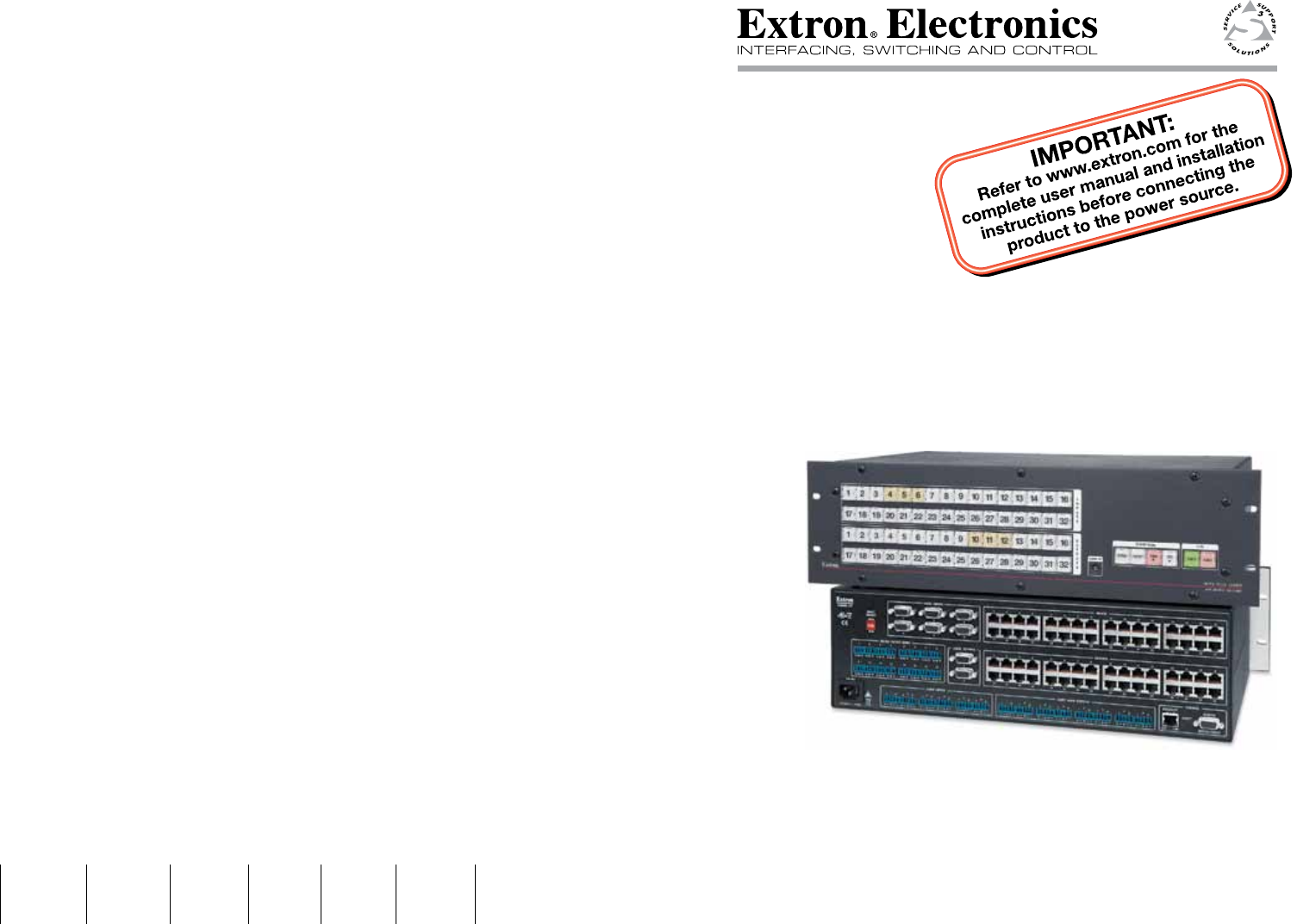
Introduction, cont’d MTPX Plus Series Matrix Switcher 2 Chapter Two Installation Rear Panel Front Panel 1-6 MTPX Plus Series • Introduction Refer also to the MTPX Plus User’s Manual at www.extron.com.
Installation Rear Panel 7 LOCAL INPUTS RGB 4 LOCAL ON 2 3 1 2 L 2 3 R 3 L R 4 L 12 3 Tx Rx 8 Tx Rx 1 2 3 4 9 10 11 12 13 6 7 8 1 2 3 4 5 6 7 8 14 15 16 9 10 11 12 13 14 15 16 8 a RESET 7 Tx Rx R MONO AUDIO OUTPUTS 1 Tx Rx Tx Rx REMOTE R Tx Rx OUTPUTS INPUTS 5 INPUT SELECT AUDIO 2 2 Tx Rx 3 RJ - 45 1 1 Tx Rx CONTROL RS - 232 OUTPUT INSERT 3 4 5 6 LAN RGB RGB 1 disconnect their power cords.
Installation, cont’d RS-232 output inserts e RS-232 Output Insert connectors — For bidirectional RS-232 data that is routed to a specific (unswitchable) TP output, connect a serial device to one of the RS-232 Output Insert 3-pole captive screw connectors. h Local audio outputs — Connect audio devices, such as audio amplifiers or powered speakers to these two, four, or eight 3.5 mm, Mono Audio (local audio) Outputs 5-pole captive screw connectors to receive unamplified, mono line level audio.
Installation, cont’d k Ethernet port — If desired, connect a network WAN or LAN hub, a control system, or a computer to the Ethernet RJ-45 port. • Network connection — Wire as a patch (straight) cable. • Computer or control system connection — Wire the interface cable as a crossover cable. N The factory default IP address is 192.168.254.254. Power l Power connector — Plug the switcher into a grounded AC source.
Front Panel Operation The key shown at right applies to all drawings in this chapter. = lit, = blinking, Saving or Recalling a Preset = unlit A "preset" is a configuration that has been stored. 1. Creating a Tie A "tie" is an input-to-output connection. Recall a preset — Press and release the Preset button. A "set of ties" is an input tied to two or more outputs. (An output can never be tied to more than one input.
Front Panel Operation, cont’d Setting the Front Panel Locks (Executive Modes) Selecting Lock mode 2 or toggling between mode 2 and mode 1 The matrix switcher has three levels of front panel security lock that limit the operation of the switcher from the front panel. The three levels are: • • • N If the switcher is in Lock mode 0 or mode 1, this procedure selects mode 2. Lock mode 0 — The front panel is completely unlocked.
Front Panel Operation, cont’d Defining the Audio/RS-232 Wire Pair and Configuring the Remote Port 1. 3. To enter Configuration mode, simultaneously press and hold the Enter, Preset, View, and Esc buttons. To change an input’s audio/RS-232 wire pair configuration, press and release the input button to toggle the configuration for that input. Press Press and hold the Control buttons. 1 C O NT R O L ENTER PRESET VIEW ESC Release the Control buttons.
Front Panel Operation, cont’d 3. Increase/decrease the level or volume by pressing the Esc (>) and View (<) buttons. button decreases the level or volume. VIEW 4. button increases the level or volume. ESC Press and release the Audio button to exit. Viewing Ties and Muting Outputs 1. Press the View button. Output buttons light for outputs that have no ties established. N If an output button blinks, that output is muted. To toggle mute on and off, press and hold the output button for 2 seconds. 2.
Remote Control and Optimizing the Video Selected SIS™ Commands You can use Simple Instruction Set (SIS) commands for operation and configuration of the switchers. You can run these commands from a PC connected to a serial port (i, j, and m on pages 2-5 and 2-6), Ethernet port (k), or USB port (n) on the switcher.
Command ASCII command Refer also to the MTPX Plus User’s Manual at www.extron.com. MTPX Plus Series • Remote Control and Optimizing the Video (host to switcher) Response (switcher to host) Additional description Create ties • Commands can be entered back-to-back in a string, with no spaces; for example; 1*1!02*02&003*003%4*24$. • The matrix switchers support 1-, 2-, and 3-digit numeric entries (1*1!, 02*02&, or 003*003%).
ASCII command (host to switcher) Response (switcher to host) Additional description Input signal level and peaking and auto calibrate Refer also to the MTPX Plus User’s Manual at www.extron.com. MTPX Plus Series • Remote Control and Optimizing the Video Set input signal level EX!*X^Ipek} IpekX!*X^] Increment input peaking EX!+Ipek} EX!-Ipek} EX!Ipek} EX!*0AADJ} IpekX!*X^] Set a specific pre-peak level for the TP input. Increase the input pre-peaking level by 1.
ASCII command Response Additional description (host to switcher) (switcher to host) Set all output skew adjustment values Example: EX@*X**X**X*Oseq} OseqX@*X**X**X*] E2*0*0*4Oseq} Oseq02*0*0*4] Increment one output skew adjustment value EX@*X(+Oseq} OseqX@*X**X**X*] Increase the X( skew plane adjustment for output X@ by 1 step (2 ns).
ASCII command (host to switcher) Response (switcher to host) Additional description Audio or RS-232 mute commands Refer also to the MTPX Plus User’s Manual at www.extron.com. MTPX Plus Series • Remote Control and Optimizing the Video Read audio or RS-232 mute X@*1Z X@*0Z X@Z Global audio or RS-232 mute 1*Z Global audio or RS-232 unmute 0*Z Audio or RS-232 mute Audio or RS-232 unmute Mute output X@ audio (audio off). AmtX@*0] Unmute output X@ audio (audio on). 1 = mute on, 0 = mute off.
ASCII command Response Additional description (host to switcher) (switcher to host) Set the audio volume to a specific value Example: X@*X1(V OutX@•VolX1(] 1*50v Out01•Vol50] Set output 1 volume to 79%. Increment volume X@+V OutX@•VolX1(] Increase volume by 1 step. 1+V Out01•Vol51] X@-V X@V OutX@•VolX1(] Audio output volume Refer also to the MTPX Plus User’s Manual at www.extron.com.
Remote Control and Optimizing the Video, cont’d IP setup 4-14 Set gateway IP address Read gateway IP address Set DHCP on or off Read DHCP on/off status Set verbose mode Read verbose mode Configure current port timeout Read current port timeout Configure global IP port timeout Read global IP port timeout X2( = Port timeout interval Refer also to the MTPX Plus User’s Manual at www.extron.com.
Remote Control and Optimizing the Video, cont’d Installing and Starting the Control Program 4-14 X2( = Port timeout interval nnn.nnn.nnn.
Remote Control and Optimizing the Video, cont’d 4. Follow the on-screen instructions. The installation program creates a C:\Program Files\Extron\ Matrix_Switchers directory and an “Extron Electronics\ Matrix Switchers” group folder.
Remote Control and Optimizing the Video, cont’d 2. Choose the comm (serial) port that is connected to the switcher or IP [LAN]. N For a comm port, check the baud rate displayed in the window. If you need to change the baud rate, click the Baud button and double-click the desired baud rate. 3. Click OK. If you selected a serial port in step 2, the Matrix Switchers Control Program is ready for operation. If you selected IP [LAN] in step 2, the IP Connection window appears.
Remote Control and Optimizing the Video, cont’d Manually setting the MTPX level and peaking If you choose not to auto calibrate, or if you want to fine tune the adjustment, you can manually set the values as follows: 1. Connect an oscilloscope (preferred) or a monitor (acceptable) to local output (VGA output) 1. 2. If using an oscilloscope, apply a white field test pattern to the input to be optimized via an MTP transmitter.
Remote Control and Optimizing the Video, cont’d 15. If either of the two the remaining colors is left shifted, repeat steps 12 and 14. 16. Repeat steps 10 through 15 for all other outputs. Tie the local input receiving the test pattern signal to the output connected to the MTP receiver to be optimized. 3.
Remote Control and Optimizing the Video, cont’d Configuring for Network Communication The first time you connect a PC to a switcher via its LAN port, you may need to temporarily change the IP settings on your PC in order to communicate with the controller. Then, change the default settings (IP address, subnet mask, and [optional] administrator name and password) in the controller in order to use the unit on an intranet (LAN) or on the Internet.
Remote Control and Optimizing the Video, cont’d 1. Start the Web browser program. 2. Click in the browser’s Address field. 3. Enter the Matrix IP address in the browser’s Address field. N 192.168.254.254 is the factory-specified default value for this field. 4. Press the keyboard Enter key. The switcher checks to see if it is password protected. If the switcher is not password protected, it checks and downloads the HTML start-up page. The switcher is ready for operation via HTML remote control.
Remote Control and Optimizing the Video, cont’d 4-28 MTPX Plus Series • Remote Control and Optimizing the Video Refer also to the MTPX Plus User’s Manual at www.extron.com.