
User Guide Manual
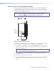
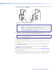
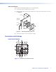
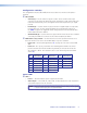
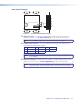
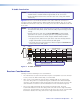
Table Of Contents
MTP U T A D • Installation and Operation 10
Rear Panel Features
OUTPUT
1
_
4
+
12 V
.5A
MAX
32
11
12
13
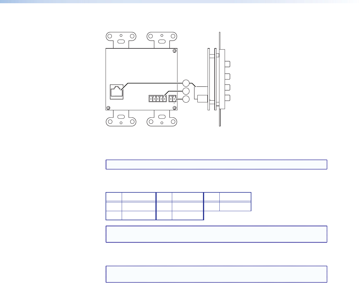
Figure 6. Transmitter Rear Panel Features
k Output connector — Connect a TP cable from this RJ-45 female connector to the
compatible receiver (see “TP Cable Termination” to wire the RJ-45 connectors).
NOTE: See the table on page 3 for recommended transmission ranges.
l Contact closure controls — To select a video input to output, momentarily tie the
assigned pin for that format to ground.
Pin Format Pin Format Pin Ground
1 Composite 3 YUV 5 Ground
2 S-video 4 PC
NOTE: The front panel Contact DIP switch (
h
) must be on (up) for contact closure
to be available.
m DC power connector — Plug the external 12 VDC, 1 A power supply into this 2-pole
captive screw connector (see "Power Supply Wiring" to wire the connectors).
NOTE: The remote power capabilities available with certain MTP models are not
supported by this unit; the transmitter and receiver both must be powered.