User Guide Twisted Pair MTP U T A D Universal Decora MTP Transmitter 68-1674-01 Rev.
Safety Instructions • English I D Power sources • This equipment should be operated only from the power source indicated on the product. This equipment is intended to be used with a main power system with a grounded (neutral) conductor. The third (grounding) pin is a safety feature, do not attempt to bypass or disable it. This symbol is intended to alert the user of the presence of uninsulated dangerous voltage within the product’s enclosure that may present a risk of electric shock.
FCC Class A Notice This equipment has been tested and found to comply with the limits for a Class A digital device, pursuant to part 15 of the FCC Rules. Operation is subject to the following two conditions: 1. This device may not cause harmful interference. 2. This device must accept any interference received, including interference that may cause undesired operation.
Conventions Used in this Guide In this user guide, the following are used: NOTE: A note draws attention to important information. TIP: A tip provides a suggestion to make working with the application easier. CAUTION: WARNING: A caution indicates a potential hazard to equipment or data. A warning warns of things or actions that might cause injury, death, or other severe consequences.
Contents Introduction............................................................ 1 About the Universal MTP Decora® Transmitter...... 1 Twisted Pair Cable................................................ 2 Transmission Distance..................................... 2 Installation and Operation.................................. 4 Installation........................................................... 4 UL Safety Requirements.................................. 4 Preparing the Site and Installing the Wall Box..
MTP U T A D User Guide • Contents vi
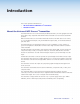
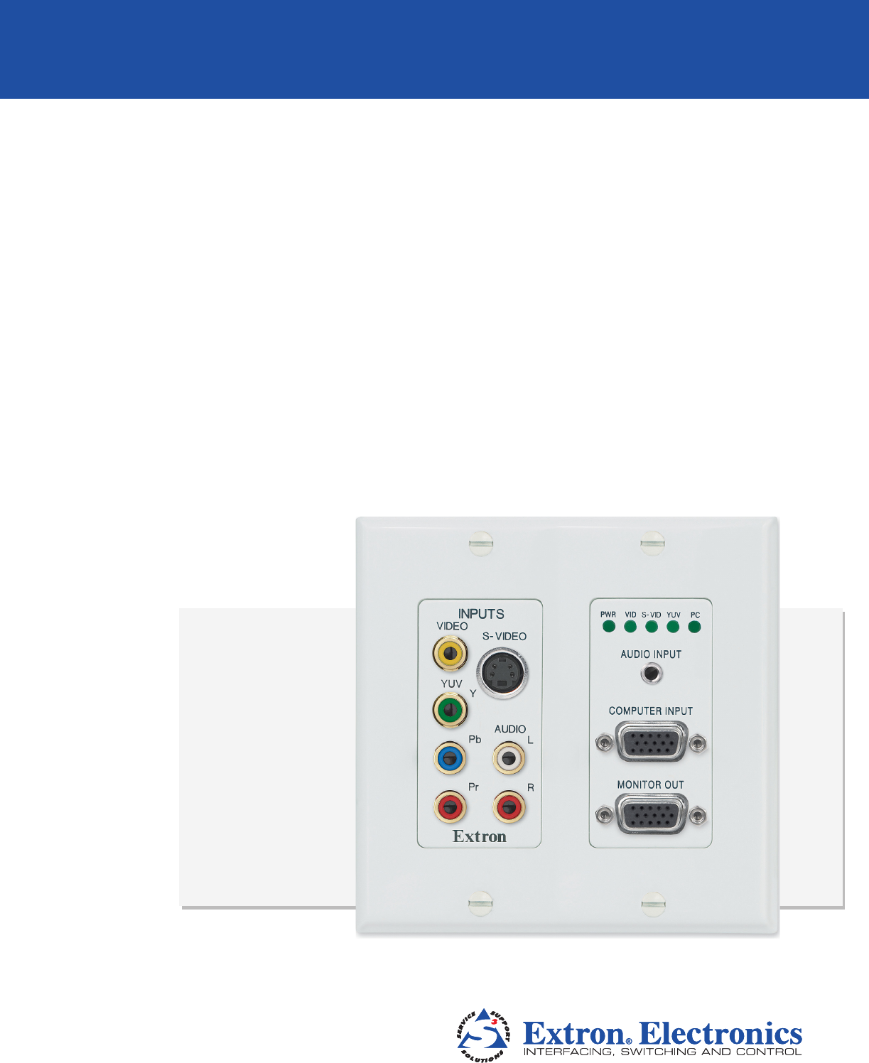
Introduction This section provides information on: • About the Universal MTP Decora® Transmitter • Twisted Pair Cable About the Universal MTP Decora® Transmitter The Extron MTP U T A D is a mini twisted pair (MTP) transmitter, in a two-gang Decora form factor, that is fully compatible with all MTP video and audio receivers and associated MTP products.
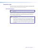
Twisted Pair Cable Twisted pair (TP) cable is much smaller, lighter, more flexible, and less expensive than coaxial cable. These TP products make cable runs simpler and less cumbersome. Termination of the cable with RJ-45 connectors is simple, quick, and economical. Transmission Distance NOTE: This transmitter provides pre-peaking, which boosts the signal before it is transmitted. The maximum distance is determined by the frequency and resolution of the signal that is input to the transmitter.
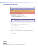
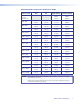
Recommended transmission distances at 60 Hz Video Format Pre-peak OFF Pre-peak On Composite, S‑video, Component Max. Distance (high quality) Max.
Installation and Operation This section discusses the installation and operation of an MTP U T A D transmitter, including: • Installation • Connections and Settings • Making Connections • Receiver Considerations • Skew Delay Compensation Installation The MTP U T A D transmitter can be installed in a two-gang electrical wall box with a Decora wall plate cover (supplied). The installation must conform to national and local electrical codes and to the wall plate size requirements.
Preparing the Site and Installing the Wall Box Choose a location that allows cable runs without interference. Allow enough depth for both the wall box and the cables. The box should be at least 2.5 inches (6.4 cm) deep to accommodate the connectors and cables. Install the cables into the wall, furniture, or conduits before installing the wall plate. NOTE: The Decora unit is 1-5/16 inch (33 m) deep and has connectors on the back side (see figure 1).
5. Secure the wall box with nails or screws, leaving the front edge flush with the outer wall or furniture surface (see figure 2). Wall Stud Wall Stud Wall Box Screws or Nails Cable Clamp Installation Cable Screws or Nails Figure 2. NOTE: Flush with Wall Surface Installing the Wall Box If attaching the wall box to • Wood — use four #8 or #10 screws or 10-penny nails. A minimum of 0.5 inch (1.3 cm) of screw thread must penetrate the wood.
Final Installation After testing and making any adjustments, do the following: 1. At the power outlet, unplug the power supply. 2. Mount the transmitter into the box and attach the supplied Decora faceplate to the unit (see figure 3). Wall Stud Wall opening is flush with edge of box. Cable Clamp V O SWITCH MODE PRE-PEAK REFRESH 50/60Hz O DI 2 T R TE CO 3 0 89A B F 123 T ITOR 67 O DI L 45 PU IN MPU C DD L.
Video Connections a Computer Input connector — Connect a computer (VGA) video source to this 15-pin HD connector for a high resolution video input. NOTES: • Input only sync signals, no video signals, on the sync pins (13 and 14). • For component video, use the R (R-Y) and R return pins (pins 1 and 6), G (Y) and G return pins (pins 2 and 7), and B (B-Y) and B return pins (pins 3 and 8). • For S-video, use the R, R return (C-chroma), G, and G return (Y-luma) pins.
Configuration switches The configuration switches (h and i) will be inaccessible once the Decora faceplate is installed. h i DIP switches • Contact (1) — Set this switch on (up) for contact closure control of the input selection. Set this switch off (down) to put the transmitter in auto switch mode (the transmitter automatically selects the highest format video input with a sync signal present). • Pre-Peak (2) — Set this switch on (up) to alter the TP signal output to compensate for long cable runs.
Rear Panel Features 11 OUTPUT 12 V 1 Figure 6. k 4 _ + .5A MAX 13 Transmitter Rear Panel Features See the table on page 3 for recommended transmission ranges. Contact closure controls — To select a video input to output, momentarily tie the assigned pin for that format to ground.
Making Connections Power Supply Wiring Figure 7 shows how to wire the power connector. 12 V Tie Wrap SECTION A–A 3/16” (5 mm) Max. Smooth Ridges A A 2-Pole Captive Screw Connector (12V) Figure 7. Power Connector Wiring CAUTION: Power supply voltage polarity is critical. Incorrect voltage polarity can damage the power supply and the MTP. Identify the power cord negative lead by the ridges on the side of the cord (see figure 7).
TP Cable Termination NOTES: • RJ-45 termination with CAT 5, CAT 5e, or CAT 6 cable must comply with the TIA/EIA T568A or TIA/EIA T568B wiring standards for all connections. • RJ-45 termination with Skew-Free A/V UTP cable must comply with TIA/EIA T568A only. Figure 8 details the recommended termination of TP cables with RJ-45 connectors in accordance with the TIA/EIA T568A or TIA/EIA T568B wiring standards.
• See the recommended transmission ranges on page 3. The recommendations in the table apply equally for a single transmitter and receiver and for a transmission daisy chain. For example, the maximum suggested range for 1024 x 768 video is 300 feet with Pre-Peak off and 500 feet with Pre-Peak on for either one transmitter and one receiver or one transmitter and three daisy-chained receivers.
Reference Information The section provides information on: • Specifications • Part Numbers • Decora Template Dimensions Specifications Video Gain ����������������������������������������������� Unity Number/signal type ������������������������ 1 set of proprietary analog signals Connectors ������������������������������������ 1 female RJ-45 Video input and loop through Number/signal type ������������������������ 1 analog RGBHV, RGBS, RGsB, RsGsBs, component video, S-video, or composite video input
Audio Number/signal type ������������������������ 1 set of proprietary analog signals Connectors ������������������������������������ 1 female RJ-45 Gain ����������������������������������������������� Unbalanced output: 0 dB; balanced output: +6 dB Frequency response ������������������������ 20 Hz to 20 kHz, ±1 dB THD + Noise ����������������������������������� 0.15% @ 1 kHz, 0.
Part Numbers MTP Transmitter and Compatible Devices NOTE: A complete transmission system requires a transmitter (MTP U T A D) and at least one MTP receiver. Transmitter MTP U T A D transmitter (white, black) NOTE: Part Number 60-1025-01, -02 The following table lists an assortment of compatible MTP receivers. In addition, the MTP U T A D is compatible with the entire MTP product line, including switchers and distribution amplifiers.
Connectors Connector Part Number CAT 6 jack (black), qty. 10 100-476-01 CAT 6 jack (red), qty. 10 100-477-01 CAT 6 jack (blue), qty. 10 100-478-01 CAT 6 jack (orange), qty. 10 100-479-01 CAT 6 jack (gray), qty. 10 100-480-01 CAT 6 jack (white), qty. 10 100-481-01 CAT 6 jack (ivory), qty. 10 100-482-01 Decora Template Dimensions To create a template, use the dimensions shown in figure 9. NOTE: The drawing is not full size or to scale. Do not scale up or print to use as a template.
Extron® Warranty Extron Electronics warrants this product against defects in materials and workmanship for a period of three years from the date of purchase.