
Setup Guide

68-1367-50
Rev. B
01 13
MTP U R Series • Setup Guide
Extron Headquarters
+800.633.9876 Inside USA/Canada Only
Extron USA - West Extron USA - East
+1.714.491.1500 +1.919.850.1000
+1.714.491.1517 FAX +1.919.850.1001 FAX
Extron Europe
+800.3987.6673
Inside Europe Only
+31.33.453.4040
+31.33.453.4050 FAX
Extron Asia
+800.7339.8766
Inside Asia Only
+65.6383.4400
+65.6383.4664 FAX
Extron Japan
+81.3.3511.7655
+81.3.3511.7656 FAX
Extron China
+4000.EXTRON
+4000.398766
Inside China Only
+86.21.3760.1568
+86.21.3760.1566
FAX
Extron
Middle East
+971.4.2991800
+971.4.2991880 FAX
Extron Korea
+82.2.3444.1571
+82.2.3444.1575 FAX
Extron India
1800.3070.3777
Inside India Only
+91-80-3055.3777
+91 80 3055 3737
FAX
© 2013 Extron Electronics All rights reserved. www.extron.com
Step 5 — Input Signal Detection
Check the displayed output is correct. The MTP U R detects the input signal format, indicated by the front panel LEDs (VID, Y/C,
YUV, RGB), and differentiates between RS-232 and audio signals. The output is then made on the appropriate connector and
all other outputs are muted.
Step 6 — Peaking and Level
RGB
PEAKING
LEVEL
MTP U R RS SEQ
Image sharpness is adjusted with the Peaking Control. Increased peaking compensates for mid- and
high-frequency detail loss. Minimum setting (full counterclockwise) is zero peaking.
Image brightness is adjusted using the Level Control. View the image and adjust the control for the best image quality.
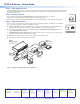
Step 7 — Skew Compensation
Pair skew can be measured with test equipment or by viewing a crosshatch test pattern. The SEQ receivers have built-in
RGB
DELAY
PEAKING
LEVEL
MTP U R RS SEQ
R
G
B
SELECT
ADJUST
SIGNAL
VID
Y/C
YUV
RGB
skew compensation capabilities. Adjust the equalization as follows:
A. Zero the skew delay for red, green, and blue by using a Tweeker or small screwdriver to press and hold the Select
button for 3 seconds. When the Red, Green, and Blue LED’s all go out, release the Select button.
B. Use UTP cable test equipment or examine the displayed image to determine which video signal (red, green, or
blue) is shifted furthest to the right.
C. Adjust the furthest left video signal towards the right by using a Tweeker or screwdriver to press and release the
Select button until the LED for the left-shifted color lights.
D. Slowly rotate the Adjust control clockwise until the shifted color is properly aligned.
E. Repeat steps C and D to align the third color if needed.
INPUT
RGB
POWER
12V
0.5A MAX
VID
Y/C
OUTPUTS
MTP U R RS
1
MONO AUDIO
2
INPUT
AUDIO
MONITOR
POWER
12V
.5A MAX
OUTPUT
MTP T 1 5H D A
PRE-PEAK
ON
OFF
L
R
INPUT
MTP T SV A
S-VIDEO
OUTPUT
12V
0.5a
MAX
RESET
ETHERNET
ACT
LINK
AUDIO INPUTS
OUTP UT S
RGB
RGB
1
2
3
1
2
3
Tx Rx
1
1
2
2
1
2
3
1
2
4
1
2
LOCAL INPUTS
RGB
RGB
LOCAL OUTPUTS
INPUT SELECT
ON
LOCAL
RJ - 45
1 2 3 4
RS-232/RS-422
REMOTE
CONTROL
LOCAL RS - 232
Tx Rx
Tx Rx
Tx Rx
Tx Rx
Tx Rx
Tx Rx
Tx Rx
INPU TS
1 2 3 4 5 6 7 8
9 10 11 12 13 14
15 16
1 2 3 4 5 6 7
8
9 10 11 12 13 14 15 16
1 2 3 4
5 6 7
8
INPUT
RGB
POWER
12V
0.5A MAX
VID
Y/C
OUTPUTS
MTP U R A
1
MONO AUDIO
2
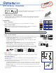
DVD-RW/-R RECORDING
Precision Cinema Progressive
Extron
MTPX 1616 Plus
MTP Matrix Switcher
Extron
MTP U R A
Universal Receiver
Extron
MTP U R RS
Universal Receiver
Extron
MTP T 15HD A
Tr ansmitter
Extron
MTP T SV A
Tr ansmitter
PC
DVD
Projector
Flat Panel
Display
Figure 1. Example of a Typical MTP U R Series Application