User’s Guide MTP U R RSA SEQ, MTP U R RS SEQ, MTP U R RS, and MTP U R A Mini Twisted Pair Universal Receivers 68-1367-01 Rev.
Precautions Safety Instructions • English This symbol is intended to alert the user of important operating and maintenance (servicing) instructions in the literature provided with the equipment. This symbol is intended to alert the user of the presence of uninsulated dangerous voltage within the product’s enclosure that may present a risk of electric shock. Caution Read Instructions • Read and understand all safety and operating instructions before using the equipment.
Precautions 安全须知 • 中文 警告 这个符号提示用户该设备用户手册中 有重要的操作和维护说明。 电源 • 该 设 备 只 能 使 用 产 品 上 标 明 的 电 源 。 设 备 必须使用有地线的供电系统供电。 第三条线 (地线)是安全设施,不能不用或跳过。 这个符号警告用户该设备机壳内有暴 拔掉电源 • 为安全地从设备拔掉电源,请拔掉所有设备后 或桌面电源的电源线,或任何接到市电系统的电源线。 露的危险电压,有触电危险。 电源线保护 • 妥善布线, 避免被踩踏,或重物挤压。 注意 阅读说明书 • 用 户 使 用 该 设 备 前 必 须 阅 读 并 理 解所有安全和使用说明。 保存说明书 • 用户应保存安全说明书以备将来使 用。 遵守警告 • 用户应遵守产品和用户指南上的所有安 全和操作说明。 维护 • 所有维修必须由认证的维修人员进行。 设备内部没 有用户可以更换的零件。为避免出现触电危险不要自己 试图打开设备盖子维修该设备。 通风孔 • 有些设备机壳上有通风槽或孔,它们是用来防止 机内敏感元件过热。 不要用任何东西挡住通风孔。 锂电池 • 不正确的更换电池会有爆炸的危险。 必
Table of Contents About this Manual ................................................................... 2 About the MTP Universal Receivers ................................ 2 TP cable advantages ................................................................. 4 Transmission distance ............................................................... 4 Receiver Jumpers ...................................................................... 5 Setting JMP1 for RS-232 communication ................................
Introduction About this Manual This manual details the installation and operation of the Extron MTP U R series of mini twisted pair universal receivers. • MTP U R RSA SEQ mini twisted pair receivers with RS-232, audio, and skew equalization N Unless separate detail is given, all information applying to the MTP U R RSA SEQ model also applies to the MTP C7 U R RSA SEQ model.
The MTP U Rs are a part of the Extron VersaTools® line of basic distribution amplifiers, switchers, transmitters, receivers, and associated video accessories. The MTP U R models receive signals on an RJ-45 connector over Extron’s Enhanced Skew-Free™ A/V UTP cable, or over Category (CAT) 5/5e/6/7 shielded twisted pair (STP), unshielded twisted pair (UTP), or foil shielded twisted pair (FTP) cable.
Introduction, cont’d TP cable advantages Twisted pair cable is much smaller, lighter, more flexible, and less expensive than coaxial cable. These TP products make cable runs simpler and less cumbersome and termination with RJ-45 connectors is simple, quick, and economical. Transmission distance The maximum distance is determined by the frequency and resolution of the signal transmitted.
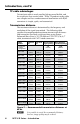
N The transmitter and receiver are designed for and perform best with Extron Enhanced Skew-Free A/V cable terminated in accordance with the TIA/EIA T 568 A wiring standard. CAT 5 cables are acceptable but less preferable. We also recommend the use of pre-terminated and tested cables. Cables terminated on site should be tested before use to ensure that they comply with Category 5/5e/6/7 specifications. The recommendations shown in the table apply for a single transmitter and receiver.
Introduction, cont’d 5. Reinstall the four screws removed in step 2. If any mounting brackets were removed in step 1, put them back into position as you reinstall the screws 6. If applicable, reinstall the receiver and reconnect all cables. N JMP1 should be set to unidirectional when an MTP DA is installed as part of the system to avoid any RS-232 /Audio detection issues.
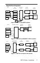
Application Diagrams Source MTPX Matrix Switcher MTP Transmitters MTP U R Receivers Display Devices Vid Vid VCR MTP T AV Audio S-Video DVD Player YUV Audio S-Video #1 #1 MTP T SV A UTP #2 MTP T 15HD A UTP #3 MTP T 15HD RS UTP #4 Audio HD-DVD Player UTP RGB RS-232 YUV Projector RGB RS-232 Audio Vid S-Video #2 PC MTP U R RSA SEQ UTP MTP U R RSA SEQ UTP RS-232 OUTPUT INSERT YUV RGB RS-232 Audio Plasma/LCD Control System Figure 5 — MTP U R and MTPX switcher SW4 MTP T 15HD
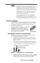
Installation Installation C Installation and service must be performed by authorized personnel only. The 1U high, quarter rack width, MTP U R receiver can be mounted on a rack shelf, to a rack without a shelf, under a desk or tabletop, or on a projector bracket. UL guidelines for rack mounted devices The following Underwriters Laboratories (UL) guidelines pertain to the safe installation of the MTP U R receiver in a rack. 1.
• RSU 129, 9.5" deep Universal 1U rack shelf kit (part #60-190-01) • RSB 129, 9.5” deep Basic 1U rack shelf (part #60-604-01) On the standard rack shelf, the MTP U R mounts in one of four locations to the rear of the rack or in one of four locations to the front of the rack. MT PT VG A RS VersaTools Basic Rack Shelf MT PT VG A RS Quarter Rack Width False Faceplate Use 2 mounting holes on opposite corners.
Installation, cont’d M TP SE R IE S Figure 9 — Attaching the back of the rack kit 1. Remove feet from the bottom of the MTP if they are installed. 2. Remove two screws from one side of the unit. Retain the screws for possible later reassembly without the bracket. 3. Attach one bracket to the side of the unit using the longer screws included in the kit. 4. Repeat steps 2 and 3 on the other side of the unit. 5. Mount the unit to the rack using the two included rack screws (figure 10).
Furniture or projector mounting Use the optional mounting kit (MBU 123, furniture, part #70-212-01, or PMK 100, projector, part #70-217-01) to mount the MTP as follows: Mounting Bolt POWER 12V .5A MAX INPUT OUTPUT Pole Mount Kit MONO AUDIO 1 2 ON H SYNC V SYNC + C SYNC + SOG VIDEO SPARE MTP R 15HD A 1 2 3 4 5 6 Projector M TP SE R IE S Figure 11 — Desk and projector mounting the MTPs 1. Remove the feet from the bottom of the MTP, if they are installed. 2.
Installation, cont’d Connections and Settings Rear panel connectors and features for the MTP U R series of receivers are shown below. MTP U R RSA SEQ 5 3 7 RS-232 R-Y Y B-Y Tx Rx MONO AUDIO L R 12V 0.5A MAX INPUT 1 2 1 RGB Y/C OUTPUTS 4 5 OUTPUTS MTP U R RS SEQ POWER VID 12V 0.5A MAX INPUT 1 2 1 RGB RS-232 Y/C Tx Rx SPARE 7 6 4 5 MTP U R RS OUTPUTS MTP U R RS POWER VID 12V 0.
a Power connector — Plug the included external 12 VDC power supply into this 2-pole captive screw connector. See “Power supply wiring” to wire the connector. b Input 1 connector — Connect one end of the cable from the transmitter. See “TP cable termination” to wire the RJ-45 connectors. C N c Do not connect these devices to a computer data or telecommunications network. If the RJ-45 connector is labelled “CAT 7 Input” (MTP C7 U R RSA SEQ model), only a CAT 7 cable should be connected. POWER 12V 0.
Installation, cont’d e Composite video output connector — Connect an appropriate display device to this female BNC connector for composite video output. f S-video output connector — Connect an appropriate display device to this 4-pin mini DIN connector for S-video output. N g Only one of the above video connectors (c through f) can be active at a time. The MTP U R device auto detects the signal format and outputs it on the appropriate connector. The other connectors are muted.
Power supply wiring This product should be connected to a UL Listed power supply and output rated at 12 VDC, 2A. N Wire the supplied male power connector (plug) as in figure 15. Smooth Ridges A A Captive Screw Connector SECTION A–A Power Supply Output Cord Tie Wrap 3" 16 (5 mm) Max. Figure 15 — Power connector wiring To verify the polarity before connection, plug in the power supply with no load and check the output with a voltmeter. C N Power supply voltage polarity is critical.
Installation, cont’d TP cable termination N RJ-45 termination must comply with TIA/EIA T 568A or TIA/EIA T 568B wiring standards for all connections. Figure 16 shows the recommended termination of cables with RJ-45 connectors in accordance with the TIA/EIA T 568A or TIA/EIA T 568B wiring standards. Either standard can be used with CAT 5/5e/6, or CAT 7 cable, but ensure that the same standard is used on both ends of the cable.
Front Panel Controls and Indicators Front panel features on the MTP U R receivers are shown below.
Installation, cont’d a b Power LED — Indicates power is applied to the MTP. c Select button (SEQ models only) — This recessed button selects the red, green, or blue video signal to adjust and resets all three video signals to a skew delay of zero nanoseconds. Use a Tweeker to press and release this button to cycle and select the red, green, or blue video signal to adjust. The selected signal is indicated by the Red, Green, and Blue LEDs (d).
The maximum setting (at the clockwise limit) provides 100% peaking. Adjust this control while viewing the displayed image to obtain the optimum picture sharpness. See “Peaking and Level Adjustment” section below for details. N To avoid possible video loss due to errors in the video format detection, the user should always start with minimal peaking and level, then only increase values as required. h Audio LED (MTP U R RSA SEQ models only) — This LED lights in audio mode by default.
Installation, cont’d N Since this product differs from the standard MTP receiver by its ability to auto detect the video format received, based on the video signal quality, it requires a reasonably adjusted signal for both level and peaking. There is some margin for over peaking but, if too much over peaking occurs, the signal may not be recognized due to signal loss. Due to analog video signal degradation when using CAT 7 cables, an MTP C7 U R RSA SEQ must be used to provide adequate peaking compensation.
N A 2-nanosecond (ns) adjustment is very fine. Up to 10 ns of delay may be necessary before a change in the display is detectable. Maximum delay possible is 62 nanoseconds. c. Use a Tweeker or other small screwdriver to press the Select button one more time to save the most recent adjustment or allow the 10-second timeout to elapse. 4. If the remaining color is left shifted, repeat step 3.
Specifications Video Gain ������������������������������������������������� Unity Video input Number/signal type ��������������������� 1 set of proprietary analog signals Connectors ������������������������������������� 1 female RJ-45 Video output Number/signal type ��������������������� 1 RGBHV, RGBS, component video (bi-level and tri-level), S-video, composite video (follows input type) Connectors MTP U R RSA SEQ, MTP C7 U R RSA SEQ ������� 1 female 15-pin HD for RGB 3 BNC female for Y, R-Y, B-Y (1) 4-p
Audio input — MTP U R RSA SEQ, MTP U R A, MTP C7 U R RSA SEQ — See MTP Series transmitters' audio output specifications Number/signal type ��������������������� 1 set of proprietary analog signals Connectors ������������������������������������� 1 female RJ-45 N 0 dBu = 0.
Specifications, cont’d General Recommended cable type MTP C7 U R RSA SEQ ������������� CAT 7 (shielded) All other models ����������������������� CAT 5/5e/6 (shielded or unshielded) External power supply ����������������� 100 VAC to 240 VAC, 50-60 Hz, external; to 12 VDC, 2 A, regulated Power input requirements ����������� 12 VDC, 0.
Included Parts Included part Replacement part number MTP U R RSA SEQ 60-869-01 MTP U R RS SEQ 60-869-02 MTP U R A 60-869-03 MTP U R RS 60-869-04 MTP C7 U R RSA SEQ 60-1016-01 Accessories Optional accessories Part number P/S 123 Multiple output 12 V power supply 60-814-01 9.5" deep 1U Universal Rack Shelf 60-190-01 9.
Extron’s Warranty Extron Electronics warrants this product against defects in materials and workmanship for a period of three years from the date of purchase.
Extron USA - West Headquarters +800.633.9876 Inside USA / Canada Only +1.714.491.1500 +1.714.491.1517 FAX Extron USA - East Extron Europe Extron Asia Extron Japan Extron China Extron Middle East +800.633.9876 +800.3987.6673 +800.7339.8766 +81.3.3511.7655 +81.3.3511.7656 FAX +400.883.1568 +971.4.2991800 +971.4.2991880 FAX +1.919.863.1794 +1.919.863.1797 FAX +31.33.453.4040 +31.33.453.4050 FAX +65.6383.4400 +65.6383.