
Setup Guide Instruction Manual

1
Product Category
IMPORTANT:
Go to www.extron.com for the
complete user guide, installation
instructions, and specifications.
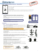
MTP T 15HD A Architectural Series • Setup Guide
The Extron MTP T 15HD A Architectural twisted pair transmitter series accept VGA and audio signals.
z MTP T 15HD A WM
z MTP T 15HD A D
z MTP T 15HD A AAP
This guide provides instructions for an installer to set up and operate these products. For detailed information,
see the MTP T 15HD A Architectural Twisted Pair Transmitters User Guide, available at www.extron.com.
Pre-installation
The MTP T 15HD A WM and D models are installed in a 1-gang electrical wall box. The
MTPT15HD A AAP is attached to a device faceplate or an AAP wall plate. Install the
electrical box or wall plate (see the MTP T 15HD A Architectural Twisted Pair Transmitters
User Guide).
Before installation, run the twisted pair (TP) and audio output cables from the output
device to the transmitter.
NOTE: The cable must be terminated using the same standard (A or B) at
both ends (see gure 1).
Run cables from the 12 VDC power supply to the transmitter.
Installation
Step 1 — Rear Panel Cabling and Adjustments
Turn off or disconnect all equipment power sources. Before mounting the transmitter, make the
following connections and adjustments:
Power — Connect the cables from the included external 12VDC power supply to the rear panel
3.5 mm, 2-pole captive screw connector.
ATTENTION: See “Power Supply Wiring” in the user guide before wiring.
Wire the 2-pole captive screw connectors as shown in the gures to the right. Plug them into the Power
connectors of the MTPs. The LED indicator on each MTP should be on when receiving power.
Grounding guidelines:
Extron MTP 15HD A products can be adversely affected by electrostatic discharge
(ESD)
if they are not
grounded
corr
ectly
.
To prevent malfunctions or product damage, an experienced installer can correctly ground an
Extron MTP 15HD A Architectural series product by grounding the power input port. Insert one end of the
grounding wire to the negative
or
ground pin on the power input connector (see the gure to the right).
Tie the other end of
the
wir
e
to an earth
ground.
If you have any questions about how to ground a product in a specic application, contact an
Extron
technical
support
specialist.
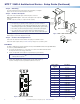
Pre-Peaking — For long cable runs, set the rear panel pre-peaking switch
to On (see the images to the right). For detailed information, see the
MTPT15HD A Architectural Twisted Pair Transmitters User Guide.
Output Cabling — Connect the TP cable to the rear panel RJ-45 connector.
Audio Cabling — For local stereo output, insert stripped audio cable into the rear panel, direct
insertion, 3.5 mm, 5-pole captive screw connector (see the figure below).
EDID Configuration (A D units) — See the EDID Minder section on the rear of this Setup Guide
for information on configuring the EDID.
12345678
Insert Twisted
Pair Wires
Pins:
NOTE: If you are using Enhanced Skew-Free™
A/V cable, use the TIA/EIA T568A standard only.
Pin
1
2
3
4
5
6
7
8
T568A
Wire Color
White-green
Green
White-orange
Blue
White-blue
Orange
White-brown
Brown
T568B
Wire Color
White-orange
Orange
White-green
Blue
White-blue
Green
White-brown
Brown
Figure 1. TP Termination Diagram
AUDIO IN
MTP T 15HD A
COMPUTER IN
Ridges
Smooth
AA
Power Supply
Output Cord
SECTION A–A
Captive Screw
Connector
0.2" (5 mm) MAX
MTP T 15HD A D Power Supply Wiring
50ON
OFF 60
Hz
PRE-
PEAK
ON
OFF
PRE-
PEAK
MTP T 15HD A D MTP T 15HD WM and AAP
Balanced Stereo Input
Tip
Ring
Sleeve (s)
Tip
Ring
LR
Unbalanced Stereo Input
Tip
Sleeve
Tip
Sleeve
LR
ATTENTION:
Potential damage to property.
For unbalanced audio, connect the sleeves
to the center contact ground.
DO NOT connect the sleeves to the
negative (-) contacts.
Ridges
Smooth
AA
Power Supply
Output Cord
SECTION A–A
Captive Screw
Connector
0.2" (5 mm) MAX
MTP T 15HD WM and AAP Power Supply Wiring
Power Supply
Output Cord
SECTION A–A
Ridges
Smooth
AA
Tie
Wrap
POWER
12V
.5A MAX
Rear
Panel
Ridges
Earth
Ground
3/16"
(5 mm)
Max.