
User Manual

MTP T 15HD A Architectural Plates • Installation
Installation
5
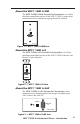
Installing the MTP T 15HD A WM and
MTP T 15HD A D
The MTP T 15HD A WM and MTP T 15HD A D can be installed
in a one-gang electrical wall box, with the MTP T 15HD A D
fitting into a Decora wall plate cover (supplied). If a suitable
wall box is already installed, follow steps 5 through 8 below. To
install a new wall box, follow all the steps below. Underwriters
Laboratories (UL) Listed wall boxes are recommended.
The installation must conform to national and local electrical
codes and to the wall plate’s size requirements.
The following Underwriters Laboratories (UL) requirements
pertain to the installation of the MTP T 15HD A architectural
series into a wall or furniture.
1. These units are not to be connected to a centralized DC
power source or used beyond their rated voltage range.
2. These units must be installed in UL listed junction boxes.
3. These units must be installed with conduit in accordance
with the National Electrical Code
Preparing the site and installing the wall box
Choose a location that allows cable runs without interference.
Allow enough depth for both the wall box and the cables. The
box should be at least 2.5 inches (6.4 cm) deep to accommodate
the connectors and cables. Install the cables into the wall,
furniture, or conduits before installing the wall plate.
1. If a wall box is not available to use for a template, use the
template on page 13. If installing directly into furniture,
cut out the center portion of the template.
2. Place the template (or the wall box) against the installation
surface, and mark the guidelines for the opening.
3. Cut out the material from the marked area.
4. Insert the wall box into the opening. The box or the wall
plate’s rear connectors should fit easily into the opening.
Enlarge or smooth the edges of the opening as needed.
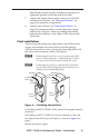
5. With the power supply disconnected, feed cables for the
output devices through the opening and through the wall
box punch-out holes, securing them with cable clamps to
provide strain relief.
6. Trim back and/or insulate exposed cable shields with heat
shrink to reduce the chance of short circuits.
To prevent short circuits, the outer foil shield can be cut
back to the point where the cable exits the cable clamp.