
User Manual

MTP T 15HD A Architectural Plates • Installation
6
Both braided and foil shields should be connected to an
equipment ground at the other end of the cable.
7. Connect the output device cables to the rear of the MTP
architectural wall plate. See "Rear panel features" on
page 9 for connector wiring details.
8. Connect input devices (see "Front panel features" on
page 8 for connector details), restore the power supply,
and test the wall plate. Make any cabling adjustments
before final installation as the cables will be inaccessible
afterwards
Final installation
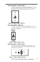
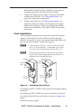
After testing and making any adjustments, turn off the power
supply and carefully insert the wall box into the opening.
Attach it with nails or screws, leaving the front edge flush with
the outer wall or furniture surface. See figure 4.
N If attaching the wall box to wood, use four #8 or #10
screws or 10-penny nails. A minimum of 0.5 inches
(1.3 cm) of screw thread must penetrate the wood.
N If attaching the wall box to metal studs or furniture,
use four #8 or #10 self-tapping sheet metal screws or
machine bolts with matching nuts.
Installation
Cable
Cable
Clamp
Wall Stud
Screws
or Nails
Wall Stud
Installation
Cable
Cable
Clamp
Screws
or Nails
Figure 4 — Installing the wall box
If installing an MTP T 15HD A WM, mount the faceplate directly
to the box.
If installing an MTP T 15HD A D, mount it directly to the wall
box, then attach the Decora wall plate, as shown in figure 5 on
page 7.
Restore the power supply.