
User Guide Manual

MTP Series • Installation 15
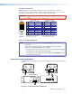
Receiver Output Connections
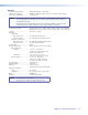
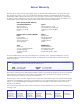
See figure 20 to identify the receivers rear panel output connections. The figures show all of
the combinations of connectors that you may encounter with your MTP receiver.
MTP R AV RCA,
Rear Panel
MTP R AV,
Rear Panel
MTP R SV A RCA,
Rear Panel
MTP R SV A,
Rear Panel
OUTPUT
MTP R AV RCA
INPUT
VIDEO
12V
0.5a MAX
L R
OUTPUT
MTP R SV A
L R
INPUT
S-VIDEO
12V
0.5a MAX
OUTPUT
MTP R SV A RCA
INPUT
S-VIDEO
12V
0.5a MAX
L
R
OUTPUT
MTP R AV
L R
INPUT
VIDEO
12V
0.5a MAX
9 9
10
11
8 8
10
11
Figure 20. Output Connector Wiring
h
S-video connector (SV models) —
Connect an S-video device to this 4-pin mini DIN
connector.
i Composite video connector (AV models) — Connect a composite video device to
this BNC connector.
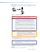
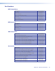
j Captive screw audio connector (MTP R SV A, MTP R AV) — Connect a balanced
or unbalanced audio device, such as an audio amplifier, to this 3.5 mm, 5-pole captive
screw connector (see figure 21 to properly wire the output connector).
LR
LR
Unbalanced Stereo Input
Balanced Stereo Input
(high impedance)
(high impedance)
Ring
Sleeve (s)
Tip
Sleeve
Tip
Sleeve
Tip
Tip
Ring
Do not tin the wires!
Figure 21. Captive Screw Connector Wiring for Audio Output
NOTE: Some receivers do not have audio connections.
CAUTIONS: • Connect the sleeve to ground (Gnd). Connecting the sleeve to a
negative (-) terminal will damage the audio output circuits.
• The length of the exposed (stripped) portion of the copper wires is
important. The ideal length is 3/16 inches (5 mm).
• Longer bare wires can short together.
• Shorter bare wires are not as secure in the direct insertion connec-
tors and could be pulled out.
k RCA audio connectors (RCA models) — Connect a stereo audio device to these L(eft)
and R(ight) RCA connectors.