User Guide Twisted Pair MTP Series Video and Audio Twisted Pair Transmitters and Receivers 68-732-01 Rev.
Safety Instructions • English I D Power sources • This equipment should be operated only from the power source indicated on the product. This equipment is intended to be used with a main power system with a grounded (neutral) conductor. The third (grounding) pin is a safety feature, do not attempt to bypass or disable it. This symbol is intended to alert the user of the presence of uninsulated dangerous voltage within the product’s enclosure that may present a risk of electric shock.
FCC Class A Notice This equipment has been tested and found to comply with the limits for a Class A digital device, pursuant to part 15 of the FCC Rules. Operation is subject to the following two conditions: 1. This device may not cause harmful interference. 2. This device must accept any interference received, including interference that may cause undesired operation.
Conventions Used in this Guide In this user guide, the following are used: NOTE: A note draws attention to important information. TIP: A tip provides a suggestion to make working with the application easier. CAUTION: WARNING: A caution indicates a potential hazard to equipment or data. A warning warns of things or actions that might cause injury, death, or other severe consequences. Copyright © 2011 Extron Electronics. All rights reserved.
Contents Introduction............................................................ 1 Operation............................................................... 16 About the MTP Transmitters and Receivers........... 1 TP Cable Advantages........................................... 2 Transmission Distance.......................................... 2 Front Panel Features........................................... 16 Troubleshooting — Skew Delay Compensation..................................................
MTP Series • Contents vi
Introduction This section introduces the MTP transmitters and receivers. Topics discussed in this section are: • About the MTP Transmitters and Receivers • TP Cable Advantages • Transmission Distance About the MTP Transmitters and Receivers The Extron MTP transmitters and receivers provide a system for long-distance distribution of NTSC, PAL, or SECAM video and audio.
TP Cable Advantages Twisted pair (TP) cable is much smaller, lighter, more flexible, and less expensive than coaxial cable. These TP products make cable runs simpler and less cumbersome. Termination of the cable with RJ-45 connectors is simple, quick, and economical.
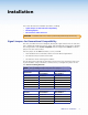
Installation This section describes the installation procedures, including: • Signal Jumpers for Generational Compatibility • Mounting Options • Panel Features and Connections CAUTION: Installation and service must be performed by authorized personnel only. Signal Jumpers for Generational Compatibility Over time, the MTPs have been redesigned, affecting the signal content of the TP cable wire pairs, changing the audio from stereo to mono, and eliminating the remote power capability.
Setting the Jumpers on Non AAP Models Figure 1. SHARP GAIN 1. Remove and retain the four screws (two on each side of the unit) that secure the cover to the MTP (see figure 1). Removing the MTP Cover 2. For the receiver, slide the cover slightly forward to clear the front panel adjustment knobs. 3. Lift the cover straight up. 4. If the transmitter or receiver is an audio unit, remove and retain the two screws that secure the audio board to the main (video) board (see figure 2).
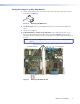
5. Locate the jumper blocks (see figure 3) on the video board. Shift the jumper to the alternate location. Mono (default jumper position) Compatible with new model transmitter/receivers. Cannot remotely power transmitter/receiver Transmitter Front Panel Transmitter Rear Panel Receiver Front Panel Receiver Rear Panel Stereo Compatible with old model transmitter/receivers. Can remotely power transmitter/receiver. Figure 3. Video Board Jumper Locations 6.
Setting the Jumpers on AAP Transmitters 1. Remove and retain the two screws that secure the back cover to the MTP (see figure 5). 1. Remove these screws. 2. Carefully pull the RJ-45 connector through this hole. OUTPUT − + POWER 12V 0.5A MAX Figure 5. Removing the MTP Cover 2. Pull the cover out of the way, carefully twisting the RJ-45 connector as necessary to slide it through the hole in the cover marked “Output.” 3.
Mounting Options UL Requirements The following Underwriters Laboratories (UL) requirements pertain to the installation of the MTP transmitter or receiver into a rack. 1. Elevated operating ambient — If the equipment is installed in a closed or multi‑unit rack assembly, the operating ambient temperature of the rack environment may be greater than room ambient. Therefore, consider installing the equipment in an environment compatible with the maximum ambient temperature (TMA) specified by the manufacturer. 2.
Rack Shelf Quarter Rack Width False Front Face Plate Eighth Rack Width False Front Face Plate DIS MD TR AS IBU TIO ER N AM IES PL IFIER (2) 4-40 x 3/16" Screws Figure 9. Mounting the MTPs on a Standard Rack Shelf Figure 8. Mounting the MTPs on a Rack Shelf Rack Mounting Instructions On the standard rack shelf, the MTP mounts in one of eight locations to the rear of the rack or in one of eight locations to the front of the rack. 1. Remove the feet from the bottom of the MTP, if installed. 2.
3. For furniture mounting — a. Hold the MTP with the attached brackets against the underside of the mounting surface. Mark the bracket screw hole locations on the mounting surface. b. Drill 3/32 inches (2 mm) diameter pilot holes, 1/4 inch (6.3 mm) deep in the mounting surface at the marked screw locations. c. Insert #8 wood screws into the four pilot holes. Tighten each screw into the mounting surface until just less than 1/4 inch of the screw head protrudes. d.
Panel Features and Connections Transmitter Input Connections Figure 12 shows all of the combinations of video and audio input connectors that you may encounter with your MTP transmitter. NOTE: Some transmitters do not have audio connections. INPUT L R L 3 12V 0.5a MAX S-VIDEO INPUT R 3 OUTPUT MTP T AV MTP T SV A, 1 Rear Panel INPUT 4 4 L R S-VIDEO L OUTPUT R 12V 0.
CAUTIONS: • The length of the exposed (stripped) portion of the copper wires is important. The ideal length is 3/16 inches (5 mm). Longer bare wires can short together. Shorter bare wires are not as secure in the direct insertion connectors and could be pulled out. • The captive screw audio connector can easily be inadvertently plugged partially into one receptacle and partially into an adjacent receptacle. This misconnection could damage the audio output circuits.
Transmitter and Receiver Throughput Connections Figure 16 identifies the connections between the transmitter and receiver. MTP Transmitters MTP Receivers INPUT L 12V 0.5a MAX OUTPUT R S-VIDEO L OUTPUT 12V 0.5a MAX MTP T SV A RCA R S-VIDEO INPUT MTP R SV A RCA 5 L 12V 0.5a MAX 5 INPUT R VIDEO L OUTPUT 12V 0.5a MAX MTP T AV OUTPUT INPUT R VIDEO MTP R AV 5 OUTPUT − + POWER 12V 0.5A MAX Figure 16.
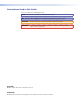
TP cable termination Figure 17 details the recommended termination of TP cables with RJ-45 connectors in accordance with the TIA/EIA T 568A or TIA/EIA T 568B wiring standards. You can use either standard, but ensure that you use the same standard on both cable ends. WARNING: Damage may occur to the unit if TP cables are miswired as crossover cables.
f Power connector — Plug the external 12 VDC power supply into this 2-pole captive screw connector on both the transmitter and the receiver. Figure 19 shows how to wire the connectors. Smooth A Ridges A SECTION A–A Power Supply Output Cord Tie Wrap 3 5 Captive Screw Connector Figure 19. Power Connector Wiring WARNING: The two power cord wires must be kept separate while the power supply is plugged in. Remove power before wiring.
Receiver Output Connections See figure 20 to identify the receivers rear panel output connections. The figures show all of the combinations of connectors that you may encounter with your MTP receiver. 10 MTP R SV A, Rear Panel L MTP R SV A RCA, Rear Panel OUTPUT OUTPUT R 11 L 12V 0.5a MAX S-VIDEO INPUT 12V 0.5a MAX MTP R SV A MTP R AV, Rear Panel L 10 8 R S-VIDEO INPUT MTP R SV A RCA 8 MTP R AV RCA, Rear Panel OUTPUT OUTPUT R 11 L 12V 0.5a MAX VIDEO INPUT MTP R AV 12V 0.
Operation This section describes: • Front Panel Features • Troubleshooting — Skew Delay Compensation Front Panel Features 1 SHARP 2 C GAIN 3 MTP R S-video Receiver Front Panel Y GAIN SHARP 1 GAIN MTP R Composite Video Receiver Front Panel 3 3 2 Figure 22. MTP Receiver Front Panels a b c Power LED — When lit, this LED indicates power is applied to the MTP. Sharpness — Adjusts the output image sharpness for long cable runs.
Reference Information This section provides information on: • Specifications • Part Numbers Specifications Video Gain ���������������������������������������������� Unity Differential phase error ������������������ <1.0º at 3.58 MHz and 4.43 MHz Differential gain error �������������������� <1.0% at 3.58 MHz and 4.
Sync Standards ��������������������������������������� NTSC 3.58, NTSC 4.
General Recommended cable type �������������� CAT5/5e/6 (shielded or unshielded) External power supply �������������������� 100 VAC to 240 VAC, 50-Hz, external; to 12 VDC, 1.0 A, regulated Power input requirements �������������� 12 VDC, 0.2 A NOTES: • If the distance between the transmitter and receiver is less than 500 feet (150 m) and if the internal jumper is in setting 2, you can connect a power supply to only one device in a transmitter/receiver pair.
Part Numbers MTP Transmitters Description Part Numbers MTP T SV A 60-540-52 MTP T SV A RCA 60-540-62 MTP T SVA AAP (black, white) 70-362-22, 23 MTP T AV 60-540-51 MTP T AV RCA 60-540-61 MTP T AV AAP (black) 70-361-22 MTP Receivers Description Part Numbers MTP R SV A 60-541-52 MTP R SV A RCA 60-541-62 MTP R AV 60-541-51 MTP R AV RCA 60-541-61 AAP Accessories Accessories Part Numbers AAP 102 panel (black, white) 60-300-02, 03 AAP 104 panel (black, white, RAL9010 white) 60-301-02,
Cables and Connectors NOTE: Enhanced Skew-Free™ A/V UTP cables are not recommended for Ethernet/LAN applications.
Extron Warranty Extron Electronics warrants this product against defects in materials and workmanship for a period of three years from the date of purchase.