User’s Manual MTP R 15HD RSA D MTP 15HD Decora Receiver 68-1463-01 Rev.
Precautions Safety Instructions • English This symbol is intended to alert the user of important operating and maintenance (servicing) instructions in the literature provided with the equipment. This symbol is intended to alert the user of the presence of uninsulated dangerous voltage within the product’s enclosure that may present a risk of electric shock. Caution Read Instructions • Read and understand all safety and operating instructions before using the equipment.
安全须知 • 中文 警告 这个符号提示用户该设备用户手册中 有重要的操作和维护说明。 电源 • 该 设 备 只 能 使 用 产 品 上 标 明 的 电 源 。 设 备 必须使用有地线的供电系统供电。 第三条线 (地线)是安全设施,不能不用或跳过。 这个符号警告用户该设备机壳内有暴 拔掉电源 • 为安全地从设备拔掉电源,请拔掉所有设备后 或桌面电源的电源线,或任何接到市电系统的电源线。 露的危险电压,有触电危险。 电源线保护 • 妥善布线, 避免被踩踏,或重物挤压。 注意 阅读说明书 • 用 户 使 用 该 设 备 前 必 须 阅 读 并 理 解所有安全和使用说明。 保存说明书 • 用户应保存安全说明书以备将来使 用。 遵守警告 • 用户应遵守产品和用户指南上的所有安 全和操作说明。 维护 • 所有维修必须由认证的维修人员进行。 设备内部没 有用户可以更换的零件。为避免出现触电危险不要自己 试图打开设备盖子维修该设备。 通风孔 • 有些设备机壳上有通风槽或孔,它们是用来防止 机内敏感元件过热。 不要用任何东西挡住通风孔。 锂电池 • 不正确的更换电池会有爆炸的危险。 必须使用与 厂家推荐的相同
Table of Contents About the MTP 15HD Decora® Receiver ................................. 1 Twisted Pair (TP) Cable Advantages ........................................ 1 Transmission distance ........................................................................ 1 Installation ........................................................................................... 4 UL/safety requirements .....................................................................
Introduction About the MTP 15HD Decora® Receiver The Extron MTP R 15HD RSA D is a mini twisted pair (MTP) receiver that auto-detects between audio or RS-232 serial data on the audio/RS-232 wire pair. The receiver fits into a Decora wall plate and is compatible with the entire line of Extron MTP 15HD transmitters and associated MTP products. The Extron MTP transmitters and receivers consist of a system used for long-distance distribution of VGA or other high resolution video, audio, or RS-232 communications.
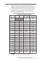
The maximum distance is determined by the frequency and resolution of the signal that is input to the transmitter. The table below specifies the recommended maximum transmission distances and transmitter Pre-Peak switch positions (refer to the applicable transmitter manual) using Extron Enhanced Skew-Free A/V UTP cable or UTP CAT 5, 5e, or 6 cable, terminated with RJ-45 connectors.
Introduction, cont’d 3 N Resolutions marked with an asterisk (*) in the table on page 2 have the same range specifications at 75 Hz. N The MTP units are designed for and perform best with Extron Enhanced Skew-Free A/V cable terminated in accordance with the TIA/EIA T 568 A wiring standard. CAT 5, 5e, and 6 cables are acceptable, but less preferable. We also recommend the use of preterminated and tested cables.
Installation and Operation Installation The MTP R 15HD RSA D receiver can be installed in a one-gang electrical wall box with a Decora wall plate cover (supplied). The installation must conform to national and local electrical codes and to the wall plate’s size requirements. UL/safety requirements The following Underwriters Laboratories (UL) requirements pertain to the installation of the Decora receiver into a wall or furniture. 1.
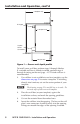
Installation and Operation, cont’d 2.50 (63.5 mm) TP Pigtail 1.50 (38.1 mm) Captive Screw Connectors Junction Box 1.85 (47 mm) Figure 1 — Decora unit depth profile To install a new wall box, perform steps 1 through 9 below. If a suitable wall box is already installed, perform steps 6 through 9 starting on the next page. A UL Listed wall box is recommended. 1. If a wall box is not available to use for a template, use the dimensions on page 21 to create a template.
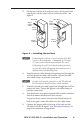
5. Secure the wall box with nails or screws, leaving the front edge flush with the outer wall or furniture surface. See figure 2. Wall Stud Signal Output Cable Cable Clamp Screws or Nails Wall Stud Signal Output Cable Cable Clamp Screws or Nails Figure 2 — Installing the wall box N If attaching the wall box to wood, use four #8 or #10 screws or 10-penny nails. A minimum of 0.5 inches (1.3 cm) of screw thread must penetrate the wood.
Installation and Operation, cont’d 10. Connect a video and an RS-232 and/or audio device to the front panel. See "Front panel features" on page 10 for connector details. 11. Restore the power supply, and test the transmitter/receiver system. Make any cabling adjustments before final installation, as the cables will be inaccessible afterwards. Final installation After testing and making any adjustments, do the following: 1. At the power outlet, unplug the power supply. 2.
Connections and Settings See figure 4 to identify the rear and front panel connections on the receiver. MTP 15HD RSA D Rx Rear Panel MTP 15HD RSA D Rx Front Panel 2 7 H SYNC + V SYNC + C SYNC SOG VIDEO Bi-RS232 INPUT 3 H SYNC + V SYNC + C SYNC SOG VIDEO Bi-RS232 6 LEVEL PEAKING AUDIO RS-232 5 Tx Rx OUTPUT 4 1 Figure 4 — Receiver’s features Rear panel features a DC power connector — If applicable, plug the external 12 VDC power supply into this 2-pole captive screw connector.
Installation and Operation, cont’d N For H Sync + and V Sync +, most devices use negative sync. N Set the Composite Sync, SOG, and Video DIP switches as shown in the table below for the various input and output video formats. Composite Sync (C Sync) switch — Set this switch on (right) for RGBS or off (left) to output RGBHV or RGsB video. See the table below.
Front panel features d e Output video connector — Connect a projector or other high resolution video device to this 15-pin HD connector. Audio RS-232 output connector — Insert a 3.5 mm, 5-pole captive screw connector into this jack for mono audio and/or a RS-232 serial output. See "Audio/RS-232 cable termination" on page 14 to wire the connector.
Installation and Operation, cont’d Making Connections Power supply wiring Figure 5 shows how to wire the power connector. 2-Pole Captive Screw Connector Tie Wrap 3/16” (5 mm) Max. SECTION A–A Smooth Ridges A A Power Supply Output Cord Figure 5 — Power connector wiring C Power supply voltage polarity is critical. Incorrect voltage polarity can damage the power supply and the MTP. Identify the power cord negative lead by the ridges on the side of the cord (figure 5).
Use the supplied tie-wrap to strap the power cord to the extended tail of the connector. Alternatively, an optional Extron PS 124 Universal 12 VDC Power Supply (part #60-1022-01) can power multiple Extron 12 VDC devices using only one AC power connector. TP cable termination N RJ-45 termination with CAT 5, CAT 5e, or CAT 6 cable must comply with the TIA/EIA T568A or TIA/EIA T568B wiring standards for all connections. RJ-45 termination with Skew-Free A/V UTP cable must comply with TIA/EIA T568A only.
MTP R 15HD RSA D • Installation and Operation Pins: RJ-45 Connector 12345678 Pin Insert Twisted Pair Wires T568A T568B Wire color Wire color Video input (via transmitter) RGB Component S-video Audio/RS-232 input Composite Stereo audio 1 White-green White-orange Red+/V. sync+ R-Y+ Chroma (C)+ Reserved 2 Green Orange Red–/V.
RS-232 function When the audio/RS-232 portion of the TP link is RS-232, it is either unidirectional or bidirectional, selectable by a DIP switch. N By default, the RS-232 portion of the TP link is unidirectional only from the transmitter to the receiver. If there is only one receiver in the system, you can set it to be bidirectional. When bidirectional is selected, the receiver can receive commands from the transmitter as well as pass RS-232 responses back to the transmitter.
Installation and Operation, cont’d N Up to seven standard receivers (MTP RL 15HD RS and MTP RL 15HD A, with or without SEQ) can be connected in series between the transmitter and the MTP R 15HD RSA D. This daisy chain is accomplished using the standard receivers' Buffered Output connectors. The total distance from the transmitter’s TP output to the last receiver in the chain should not exceed the recommended distance for the resolution being used.
Reference Information Specifications Video Gain ������������������������������������������������� Unity Number/signal type ��������������������� 1 set of proprietary analog signals Connectors ������������������������������������� 1 female RJ-45 on a pigtail Video input — See MTP Series Transmitters' video output specifications.
Reference Information, cont’d THD + Noise ���������������������������������� 0.15% @ 1 kHz, 0.3% @ 20 kHz at nominal level S/N �������������������������������������������������� >70 dB at maximum output (unweighted) CMRR ���������������������������������������������� >43 dB @ 20 Hz to 20 kHz Audio output Number/signal type ��������������������� 1 mono, balanced/unbalanced Connector ��������������������������������������� (1) 3.
Temperature/humidity ���������������� Storage: -40 to +158 °F (-40 to +70 °C)/ 10% to 90%, noncondensing Operating: +32 to +122 °F (0 to +50 °C)/ 10% to 90%, noncondensing Cooling ������������������������������������������� Convection, no vents Furniture mount ���������������������������� Yes, using a standard electrical wall box or Decora® size mud ring Enclosure type ������������������������������� Metal Enclosure dimensions Faceplate ����������������������������� 2.6" H* x 1.3" W x 0.24" D (6.
Reference Information, cont’d Part Numbers MTP receiver and compatible transmitters and switchers N A complete transmission system requires at least one transmitter and one MTP receiver (the MTP R 15HD RSA D, for this manual).
Cables N Enhanced Skew-Free™ A/V UTP cables are not recommended for Ethernet/LAN applications. Enhanced Skew-Free™ A/V cable Part number Enhanced Skew-Free A/V cable (cut, various lengths) 26-569-xx Enhanced Skew-Free A/V 1000' (Bulk) (non-plenum) 22-141-03 Plenum enhanced Skew-Free A/V 1000‚ (Bulk) 22-142-03 Connectors Connector Part number CAT 6 jack (black), qty. 10 100-476-01 CAT 6 jack (red), qty. 10 100-477-01 CAT 6 jack (blue), qty. 10 100-478-01 CAT 6 jack (orange), qty.
Reference Information, cont’d Decora Template Dimensions If you need to create a template, use the dimensions shown in figure 8 below. N The drawing is not full size or to scale. Do not scale up or print to use as a template. Full size templates are available online at www.extron.com 2.79" (7.09 cm) Top Panel 1.9" (4.83 cm) 4.50" (11.43 cm) 2.8" (7.
Extron Warranty Extron Electronics warrants this product against defects in materials and workmanship for a period of three years from the date of purchase.
Extron USA - West Headquarters +800.633.9876 Inside USA / Canada Only +1.714.491.1500 +1.714.491.1517 FAX Extron USA - East Extron EMEA Extron Asia Extron Japan Extron China Extron Middle East +800.633.9876 +800.3987.6673 +800.7339.8766 +81.3.3511.7655 +81.3.3511.7656 FAX +400.883.1568 +971.4.2991800 +971.4.2991880 FAX +1.919.863.1794 +1.919.863.1797 FAX +31.33.453.4040 +31.33.453.4050 FAX +65.6383.4400 +65.6383.