
User Guide Owner's manual

Wiring Connectors
Digital Connector Pin Connector
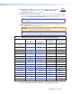
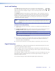
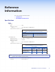
The figure below details the recommended termination of TP cables with RJ-45 connectors
in accordance with either the TIA/EIA T 568A or the TIA/EIA T 568B wiring standard.
5
Pin
1
2
3
6
7
8
4
Wire color
White-green
Green
White-orange
White-blue
Orange
White-brown
Brown
Blue
Data 0+
Data 0–
Data 1–
ID Clock–
Data 2+
Data 2–
Wire color
White-green
Green
White-orange
White-blue
Orange
White-brown
Brown
Signal
TIA/EIA T
568 A
TIA/EIA T
568 B
RJ-45 #1
ID Clock+
Data 1+Blue
CEC
HPD
RS-232
TX
+12 V
RS-232
RX
DDC data
Ground
RJ-45 #2
DDC Clk
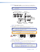
Insert Twisted
Pair Wires
RJ-45 Connector
12345678
Pins:
Figure 8. Digital Connector Wiring
NOTE: Whichever standard (TIA T 568A or T568 B) is used, the same standard must
be used on both ends of the cable.
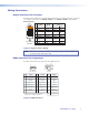
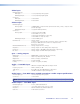
HDMI Connector Pin Assignments
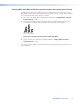
The table below defines the pinout for the HDMI protocol.
Pin Signal
1
TMDS data 2+
TMDS data 2-
TMDS data 0–
TMDS clock- +5 V power
Hot plug detect
CEC control*
Reserved
(NC)
TMDS data 1+ TMDS clock+
TMDS clock
shield
SDA
DDC / CEC
Ground
TMDS data 2
shield
Pin Pin Signal Signal
2
7 13
4 10 16
11 17
12 18
19
* CEC control on pin 13 is a proprietary
usage, not the industry standard.
14
3
TMDS data 0-
TMDS data 0
shield
8
9
SCL
15
TMDS data 1-
TMDS data 1
shield
5
6
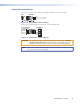
HDMI
HDMI
Type A Receptacle
Type A Plug
1
18 2
19
1
182
19
Figure 9. HDMI Connectors
MTP/HDMI U R • Cabling 7