User Guide TWISTED PAIR MTP/HDMI U R MTP Twisted Pair Universal Receiver 68-1727-01 Rev.
Precautions Safety Instructions • English Warning This symbol is intended to alert the user of important operating and maintenance (servicing) instructions in the literature provided with the equipment. Power sources • This equipment should be operated only from the power source indicated on the product. This equipment is intended to be used with a main power system with a grounded (neutral) conductor. The third (grounding) pin is a safety feature, do not attempt to bypass or disable it.
FCC Class A Notice This equipment has been tested and found to comply with the limits for a Class A digital device, pursuant to part 15 of the FCC Rules. Operation is subject to the following two conditions: 1. This device may not cause harmful interference. 2. This device must accept any interference received, including interference that may cause undesired operation.
Contents Introduction............................................................ 1 Reference Information....................................... 13 MTP/HDMI U R Description.................................. 1 Part Numbers and Accessories............................ 16 Included Parts................................................ 16 Optional Parts................................................ 16 Cabling..................................................................... 3 Rear Panel Cabling..........
MTP/HDMI U R • Contents vi
Introduction This guide contains information about the Extron® MTP/HDMI U R Twisted Pair Universal Receiver with instructions for experienced installers on how to install, configure, and operate the equipment. In this guide the following terms are applicable: • “Transmitter” refers primarily to an MTP transmitter, but could also include an HDMI 201 Tx transmitter. • “Receiver” refers to the MTP/HDMI U R receiver.
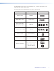
The MTP/HDMI U R ships with an external desktop 12 V, 1 A power supply that accepts 100 to 240 VAC, 50 Hz or 60 Hz input. A summary table of the MTP/HDMI U R connectivity is shown below. Feature Connectivity Digital output HDMI (1) RGBHV, RGBS output 15-pin HD (1) Component video.
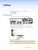
Cabling This section describes how to connect cables to the MTP/HDMI U R. • Rear Panel Cabling • Wiring Connectors Rear Panel Cabling The illustration below shows the rear panel features of the MTP/HDMI U R. 10 11 DIGITAL INPUT 1 DIGITAL OUTPUT RS-232 2 POWER 12V 0.8A MAX R-Y HDMI Y VID 3 4 5 RGB 6 SPARE MONO AUDIO 1 2 PASS THRU MTP INPUT 2 Tx Rx B-Y RS-232 Tx Rx 1 9 Y/C ANALOG OUTPUTS 7 8 Figure 2.
CAUTION: NOTE: b Always use a power supply supplied by or specified by Extron. Use of an unauthorized power supply voids all regulatory compliance certification and may cause damage to the supply and the end product. Unless otherwise stated, the AC/DC adapters are not suitable for use in air handling spaces or in wall cavities.
HDMI c Digital signal output — The MTP/HDMI U R outputs a digital HDMI signal through this female HDMI connector. See the "HDMI Connector Pin Assignments" section, for pin wiring details. d RS-232 Control Pass-thru connector — Connect a serial communications port to this 3.5 mm, 3-pole captive screw connector for bidirectional RS-232 communication (digital side). See the "Control Connector Wiring" section, to wire the connector.
f g j k Analog signal outputs — Connect suitable devices for analog signals: RGBHV, RGBS, component (Y, R-Y, B-Y), S-video (Y/C), and composite video. NOTE: The video signals detected on the MTP input are directed to the appropriate analog outputs.
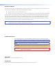
Wiring Connectors Digital Connector Pin Connector The figure below details the recommended termination of TP cables with RJ-45 connectors in accordance with either the TIA/EIA T 568A or the TIA/EIA T 568B wiring standard.
Control Connector Wiring For the 3-pole (digital side) RS-232 pass-through connector, wire as shown below: Tx/Rx Pins Connected RS-232 Device Pins Ground Transmit pin on connected unit Receive pin on connected unit Rx Tx Figure 10. 3-pole RS-232 Connector Wiring For the 5-pole (analog side) RS-232 connector, wire as shown below: Connected RS-232 Device Pins Receive Transmit Ground MTP/HDMI U R Pins Tx Rx Gnd Spare Spare Figure 11.
Operation This section of the guide discusses the operation of the MTP/HDMI U R and cover the following points: • Front Panel Overview • Level and Peaking • Signal Detection • Setting the Jumpers Front Panel Overview ANALOG SIGNAL VID AUDIO Y/C RS-232 YUV RGB 1 RGB LEVEL PEAKING DIGITAL SIGNAL MTP/HDMI U R 2 3 4 5 Figure 12. MTP/HDMI U R Front Panel Features a LED indicator — A solid green light indicates the unit is receiving power from the connected power supply.
Level and Peaking The Level adjustment knob (which can be used only on the analog signal) alters the video output voltage to affect the brightness of the displayed image. Adjust the knob while viewing the image to set the level that provides the best picture quality. RGB LEVEL PEAKING The Peaking adjustment knob adjusts the image sharpness, and is applicable only to the analog side of the device.
Setting the Jumpers The MTP/HDMI U R receiver has three jumpers on the main board: • • Jumper 1 (JMP1) controls RS-232 directional communication (bidirectional or unidirectional) JMP1 is in closed position by default, and configured to send serial data both ways, transmitter-to-receiver, receiver-to-transmitter (bidirectional). Jumpers 2 (JMP2) and 3 (JMP3) control vertical and horizontal sync respectively (negative or positive).
Setting JMP2 and JMP3 to Positive Vertical and/or Horizontal Sync Polarity Horizontal and vertical sync polarity can be set by configuring the internal jumpers on the MTP/HDMI U R main board. The default setting is negative sync (H- V-), and can be changed by resetting the position of the jumpers as follows: 1. If the unit is not already open, follow steps 1 and 2 in the “Setting JMP1 for RS-232 Communication” section. 2. Locate JMP2 and JMP3 on the main board.
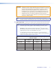
Reference Information This section provides information about: • Specifications • Part Numbers and Accessories Specifications Video MTP input Gain ���������������������������������������� Unity Maximum resolution Analog ������������������������������� Up to 2048x1080 or 1080p @ 60 Hz Signal transmission distance, analog MTP/HDMI U R Analog Signal Maximum Transmission Distances Resolutions 1024x768 @ 60 Hz Up to 600' (183 m) 1920x1200, 2048x1080 1080p @ 60 Hz Up to 400' (122 m) HDMI digital input Ma
Video input Number/signal type MTP input �������������������������������� HDMI digital input ������������������� Connectors MTP input �������������������������������� HDMI digital input ������������������� 1 set of proprietary analog signals 1 set of proprietary digital signals 1 female RJ-45 2 female RJ-45 Video output Number/signal type Analog output ������������������������� 1 RGBHV, RGBS, component video (bi-level and tri-level), S-video, composite video (follows input type) HDMI digital output ������
Control/remote — external device (pass-through) from the HDMI input Serial control port input/output ������ RS-232 via (1) 3.5 mm, 3 pole captive screw connector Baud rates �������������������������������������� Up to 38400 bps at up to 600' (183 m) (Higher data rates and distances are possible. Performance varies based on baud rate and cable length.) NOTE: Protocol is mirrored between the transmitter and the receiver.
Part Numbers and Accessories Included Parts Description Part Number MTP/HDMI U R 60-1048-01 Rubber feet (not attached) (4) External, 12 VDC, 1 A power supply PS 1210 C 70-775-01 3.5 mm, 3-pole captive screw connector for RS-232 connections IEC power cord (1) Setup Guide - MTP/HDMI U R Optional Parts Description Part Number RSU 129 (1U, 9.5" deep rack shelf kit) 60-190-01 RSB 129 (1U, 9.
Mounting This section outlines the various mounting options available for the MTP/HDMI U R: • Wall Mounting • Pole Mounting • Tabletop Placement • Rack Mounting • Under-desk Mounting • Through-desk Mounting Wall Mounting The MTP/HDMI U R can be mounted on a wall, using the optional Extron WMK 150 wall mounting kit. This allows the unit to be concealed close to wall‑mounted flat screen monitors. To mount the unit on the wall, follow the instructions provided with the WMK 150 kit.
Rack Mounting UL Guidelines for Rack Mounting The following Underwriters Laboratories (UL) guidelines are relevant to the safe installation of these products in a rack: 1. Elevated operating ambient temperature — If the unit is installed in a closed or multi-unit rack assembly, the operating ambient temperature of the rack environment may be greater than room ambient temperature.
Extron® Warranty Extron Electronics warrants this product against defects in materials and workmanship for a period of three years from the date of purchase.