User Guide Twisted Pair MTP 15HD RS Series High Resolution Video and Serial Link MTP Transmitters and Receivers 68-925-02 Rev.
Safety Instructions • English Warning This symbol is intended to alert the user of important operating and maintenance (servicing) instructions in the literature provided with the equipment. Power sources • This equipment should be operated only from the power source indicated on the product. This equipment is intended to be used with a main power system with a grounded (neutral) conductor. The third (grounding) pin is a safety feature, do not attempt to bypass or disable it.
FCC Class A Notice This equipment has been tested and found to comply with the limits for a Class A digital device, pursuant to part 15 of the FCC Rules. Operation is subject to the following two conditions: 1. This device may not cause harmful interference. 2. This device must accept any interference received, including interference that may cause undesired operation.
Contents Introduction............................................. 1 About this Guide.............................................. 1 About the MTP Transmitters and Receivers........ 2 Twisted Pair Cable Advantages...................... 3 Transmission Distance....................................... 3 Receiver Jumpering........................................... 5 Installation and Operation...................... 6 Installation and Operation Overview.................. 6 Front Panel Features..................
Introduction This section gives an overview of the user guide. This section also describes the MTP 15HD RS Series of transmitters and receivers. Topics that are covered include: zz About this Guide zz About the MTP Transmitters and Receivers zz Transmission Distance zz Receiver Jumpering About this Guide This guide contains installation, configuration, and operation information for two families of Extron MTP transmitters and receivers.
About the MTP Transmitters and Receivers The Extron MTP T 15HD RS transmitter and MTP RL 15HD RS and MTP RL 15HD RS SEQ receivers are a system for long-distance distribution of VGA or other high resolution video and RS-232 serial communications. The MTPs are a part of the Extron compact line of basic distribution amplifiers, switchers, transmitters, receivers, and associated video accessories. High resolution video is sent to the MTP transmitter on a 15-pin HD connector.
The SEQ receiver also corrects the skew delay commonly encountered when CAT 5, 5e, 6, 7, or STP201 cables are used for RGB video, component video, and S-video transmission. NOTE: An SEQ receiver should not be necessary when Extron Enhanced Skew-Free A/V UTP cable is used. Each MTP transmitter and receiver model is shipped with an external desktop 12 VDC power supply that accepts 100 VAC to 240 VAC, 50-60 Hz input.
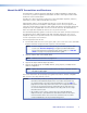
Video Format Pre-Peak Pre-Peak off on Composite, S-video, Component 640x480 800x600 1024x768* 1280x960* 1280x1024* 1360x765 1365x768 1366x768 1400x1050 1440x900 1600x1200* 1920x1200 2048x1080 HDTV 720p HDTV 1080i HDTV 1080p <300' (90 m) <300' (90 m) <300' (90 m) <300' (90 m) <250' (75 m) <250' (75 m) <250' (75 m) <250' (75 m) <250' (75 m) <250' (75 m) <250' (75 m) <250' (75 m) <250' (75 m) <250' (75 m) <250' (75 m) <250' (75 m) >350' (105 m) >350' (105 m) >350' (105 m) >350' (105 m) >300' (90 m) >300' (
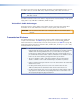
Receiver Jumpering By default, the receiver is unidirectional, configured to send serial data from the transmitter to the receiver, only. If the system has only one receiver, this jumper can be repositioned to enable bidirectional communication as follows: 1. If applicable, disconnect all cables, remove the receiver from its installation location, and remove any mounting brackets installed. 2.
Installation and Operation This section provides information on: zz Installation and Operation Overview zz Front Panel Features zz Transmitter Rear Panel Features zz Receiver Rear Panel Features zz Power Supply Wiring zz Twisted Pair Cable Termination zz Skew Delay Compensation Installation and Operation Overview Follow the steps below to properly install and operate any of the Extron MTP 15HD RS transmitters and receivers.
Front Panel Features See figure 3 below to identify the front panel features on the transmitter and receiver. 1 MTP SERIES MTP T 15HD RS transmitter 3 2 RGB LEVEL PEAKING 1 MTP SERIES MTP RL 15HD RS receiver 4 5 6 2 3 DELAY RGB RED SELECT 1 LEVEL PEAKING GREEN BLUE MTP SERIES MTP RL 15HD RS SEQ receiver Figure 3. MTP Front Panels a b Power LED — The LED indicator lights when the unit is receiving power.
d Select button (SEQ model only) — This recessed button selects the Red, Green, or Blue video signal to adjust and resets all three video signals to a skew delay of zero nanoseconds. Use a small screwdriver to press and release this button to cycle among selecting the Red, Green, or Blue video signal to adjust. The selected signal is indicated by the Red, Green, and Blue LEDs (e).
Transmitter Rear Panel Features Figure 4 shows an MTP T 15HD RS transmitter, which has all of the connectors and other features that are on either transmitter in the MTP 15HD RS series. 4 MTP T 15HD RS RS-232 PRE-PEAK Tx Rx POWER 12V .5A MAX NOTE: A “C7” label is affixed to transmitters designed for STP201 or CAT 7 cable. ON INPUT MONITOR 2 3 1 OFF 5 OUTPUT 6 Figure 4.
d RS-232 connector — Connect a serial communications port to this 3.5 mm, 3-pole captive screw connector for bidirectional RS-232 communication. Wire the connector as shown in figure 6. Connected RS-232 Device Pins Receive Transmit Ground MTP Pins Tx Rx Gnd Figure 6. RS-232 Connector Wiring NOTES: • By default, the RS-232 portion of the TP link is unidirectional only from the transmitter to the receiver.
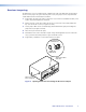
Receiver Rear Panel Features Figure 7 shows an MTP RL 15HD RS receiver, which has all of the connectors and other features that are on either receiver in the MTP 15HD RS series. 5 MTP RL 15HD RS 12V .5A MAX INPUT BUFFERED OUTPUT H SYNC + V SYNC + C SYNC SOG VIDEO END UNIT POWER RS-232 Tx Rx ON NOTE label is affixed to to NOTE: AA“C7” “C7” label is affixed receivers receiversdesigned designedfor for DTP26 STP201ororCAT CAT7 7cable. cable. 6 1 2 3 4 5 6 OUTPUT 1 3 2 4 Figure 7.
f DIP switches (RL receivers only) — A 6-pole DIP switch is used to configure the features of the MTP receivers. zz Horizontal sync (H Sync +) switch — Set this switch On (up) for positive horizontal sync or Off (down) for negative sync. zz Vertical sync (V Sync +) switch — Set this switch On (up) for positive vertical sync or Off (down) for negative sync. NOTE: zz For H Sync + and V Sync +, most devices use negative sync.
Power Supply Wiring Figure 9 below shows how to wire the connector. CAUTION: Power supply voltage polarity is critical. Incorrect voltage polarity can damage the power supply and the transmitter or receiver. Identify the power cord negative lead by the ridges on the side of the cord. To verify the polarity before connection, plug in the power supply with no load and check the output with a voltmeter.
Use the supplied tie-wrap to strap the power cord to the extended tail of the connector. As an alternative, an Extron PS 124 Universal 12 VDC Power Supply (part number 60-1022-01) can power multiple MTPs or other Extron 12 VDC devices using only one AC power connector. Twisted Pair Cable Termination Figure 10 details the recommended termination of TP cables with RJ-45 connectors in accordance with the TIA/EIA T568A or TIA/EIA T568B wiring standards.
Skew Delay Compensation CAT 5, 5e, 6, 7, and STP201 cable can lead to registration errors between the Red, Green, and Blue video signals. Pair skew can be measured with test equipment or identified by viewing a crosshatch test pattern with a critical eye to determine if either the Red, Green, or Blue video image leads (appears to the left of) the other two video images. NOTE: Unless the TP cable is changed, the skew adjustment should need to be made only once, during installation.
Reference Information This section provides information about: zz Specifications zz Part Number, Optional Accessories, Cables, and Connectors Specifications Video Gain ��������������������������������������������� Unity Number/signal type ����������������������� 1 set of proprietary analog signals Connectors ����������������������������������� 1 female RJ-45 Video input and loop-through — transmitter (MTP T 15HD RS) Number/signal type ����������������������� 1 analog RGBHV, RGBS, RGsB, RsGsBs, componen
Maximum resolution ��������������������� Up to 1920x1200 or 2048x1080 or 1080p at 300' Up to 1024x768 at 600' NOTE: Refer to the user guide for the maximum distances recommended for specific resolutions. Sync Input type (transmitters) ���������������� RGBHV, RGBS, RGsB, RsGsBs Output type (receivers) ������������������ RGBHV, RGBS, RGsB, RsGsBs Standards ������������������������������������� NTSC 3.58, NTSC 4.43, PAL, SECAM Input level (transmitters) ���������������� 3.5 V to 5.
Mounting Rack mount ������������������������������� Yes, with optional 1U deep rack shelf Furniture mount ������������������������ Yes, with optional mini under-desk mounting kit Pole mount ������������������������������� Yes, with optional pole mounting kit Enclosure type ...............................Metal Enclosure dimensions �������������������� 1.7" H x 4.3" W x 3.0" D (1U high, quarter rack wide) (4.3 cm H x 10.9 cm W x 7.6 cm D) (Depth excludes connectors.
Optional Accessories Description Part Number PS 124 multiple output 12 volt DC power supply 60-1022-01 MBB 100 (1/8 and 1/4 back of rack mounting kit) 70-367-01 MBU 123 under desk mounting kit 70-212-01 PMK 100 (1/4 rack width pole mount kit) 70-217-01 RSF 123 (3.5 inches deep, 1U rack shelf kit) 60-190-20 RSB 123 (3.5 inches deep, 1U basic rack shelf) 60-604-21 RSU 126 (6 inches deep, 1U rack shelf kit) 60-190-10 RSB 126 (6 inches deep, 1U basic rack shelf) 60-604-11 RSU 129 (9.
Mounting This section outlines the various mounting options available for the MTP 15HD RS Series transmitters and receivers: zz Tabletop Placement zz Under-desk Mounting zz Rack Mounting zz Projector Mounting Tabletop Placement Attach the four provided rubber feet to the bottom of the unit and place it in any convenient location. Under-desk and Furniture Mounting Mount the unit under a desk or podium using the optional Extron MBU 123 under desk mounting kit (part number 70‑212‑01).
Rack Mounting Procedure These units can be mounted on any of these optional rack systems, including: zz RSF 123: 3.5 inch deep, 1U rack shelf kit (part number 60-190-20) zz RSB 123: 3.5 inch deep, 1U basic rack shelf (part number 60-604-21) zz RSU 126: 6 inch deep, 1U rack shelf kit (part number 60-190-10) zz RSB 126: 6 inch deep, 1U basic rack shelf (part number 60-604-11) zz RSU 129: 9.5 inch deep, 1U rack shelf kit (part number 60-190-01) zz RSB 129: 9.
Extron Warranty Extron Electronics warrants this product against defects in materials and workmanship for a period of three years from the date of purchase.