
User Guide Rev. C Owner manual


Receiver Rear Panel Features
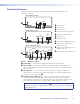
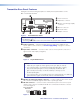
See figure 6 and the following descriptions to identify the rear panel features on the
MTP RL 15HD RS receiver.
INPUT
BUFFERED
OUTPUT
OUTPUT
POWER
12V
0.5A MAX
MTP RL 15HD RS
RS-232
RxTx
OUTPUTS
G
E
BC DA
Figure 6. Receiver Rear Panel
NOTE: Control signal ground pins may be labeled as or “G”. Audio ground pins may
be labeled as or .
The wiring and function are the same, whichever way your product is labeled.
A Power connector — Plug the included external 12 VDC power supply into this 2-pole
captive screw connector.
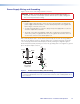
ATTENTION: Before wiring the connector, read the notes, attentions, and
warnings in the Power Supply Wiring and Grounding section on the next page.
B Input connector — Connect one end of the TP cable from the transmitter or from the
buffered output connector of an RL receiver to this RJ-45 female connector.
C Buffered output connector — Connect one end of a TP cable to this female
RJ-45 connector. Connect the opposite end of the same TP cable from the receiver
to the Input RJ-45 female connector on another receiver (see Twisted Pair Cable
Termination on page 14 to wire the RJ-45 connectors).
ATTENTION: Do not connect these devices to a computer data or
telecommunications network.
D Output video connector — Connect a projector or other high
resolution video device to this 15-pin HD connector.
NOTES:
• The video auto detection feature is sensitive to video signals with high levels,
over-peaked signals, or both, which may result in video detection issues.
• Input only sync signals (no video signals) on the sync pins (13 and 14).
• For component video, use the R (R-Y) and R return pins (pins 1 and 6),
G (Y) and G return pins (pins 2 and 7), and B (B-Y) and B return pins
(pins 3 and 8). For S-video, use the R, R return (C-chroma) (or B, B return [see
S-Video switch of
K
on page 8]), G, and G return (Y-luma) pins.
• For composite video, use the G pin and the associated return pin. For additional
genlocked video signals, use the R, B, and associated return pins.
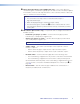
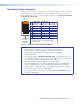
E RS-232 connector — Connect a serial communications port to this 3.5 mm, 3-pole
captive screw connector for bidirectional RS-232 communication. Wire the connector
as shown in figure 5 on page 9.
51
15 11
610
Female
MTP 15HD RS Series • Installation and Operation 11