User Guide Twisted Pair MTP 1500RL 15HD A SEQ Extended Distance Twisted Pair Receiver 68-1554-01 Rev.
Precautions Safety Instructions • English Warning This symbol is intended to alert the user of important operating and maintenance (servicing) instructions in the literature provided with the equipment. Power sources • This equipment should be operated only from the power source indicated on the product. This equipment is intended to be used with a main power system with a grounded (neutral) conductor. The third (grounding) pin is a safety feature, do not attempt to bypass or disable it.
FCC Class A Notice This equipment has been tested and found to comply with the limits for a Class A digital device, pursuant to part 15 of the FCC Rules. Operation is subject to the following two conditions: 1. This device may not cause harmful interference. 2. This device must accept any interference received, including interference that may cause undesired operation.
Conventions Used in this Guide In this user guide, the following are used: CAUTION: NOTE: TIP: A caution indicates a potential hazard to equipment or data. A note draws attention to important information. A tip provides a suggestion to make working with the application easier. WARNING: A warning warns of things or actions that might cause injury, death, or other severe consequences.
Contents Introduction............................................................ 1 Reference Information........................................ 11 MTP 1500RL 15HD A SEQ Description.................. 1 Features........................................................... 1 Transmission Distance...................................... 2 Specifications..................................................... 11 Part Numbers and Accessories............................ 13 Included Parts.............................
MTP 1500RL 15HD A SEQ • Contents vi
Introduction This manual details the installation and operation of the Extron MTP 1500RL 15HD A SEQ Twisted Pair receiver with audio and skew equalization In this guide the following terms are used: zz “Transmitter” refers specifically to the MTP transmitter. zz “Receiver” or “SEQ receiver” refers specifically to the MTP 1500RL 15HD A SEQ receiver with skew equalization.
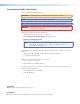
Transmission Distance The maximum transmission distance is determined by the frequency and resolution of the transmitted signal. The table below shows the maximum transmission distances (in feet and meters) and the transmitter Pre-peak switch positions using Extron Enhanced Skew-Free AV UTP cable or UTP CAT cable, terminated with RJ-45 connectors.
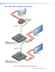
MTP 1500RL 15HD A SEQ Application Diagram RGBHV PC Audio Extron MTP T 15HD A M 15 T TP Twisted Pair Transmitter A HD EAK E-P PR ON UT TP DIO AU F OU OF OR NIT MO WER PO T V 12 MAX .5A PU IN 500’ (152 m) UTP Cable (CAT 5/5e/6) H+ V+ CSYNC SOG VIDEO END SPARE Flat Panel Display ON O O T PU MON L DI AU R RL MTP 15HD A SE Q 1500 Audio OUT T PU ED OUT ER FF BU RGBHV T PU IN Extron MTP 1500RL 15HD A SEQ MTP MTP R WE PO X V 12 A MA 1.
Installation and Setup This section describes how to connect applicable cables to the MTP 1500RL A SEQ receiver. It covers: zz Rear Panel Features zz Power Supply Wiring zz TP Cable Termination Rear Panel Features INPUT BUFFERED OUTPUT OUTPUT POWER 12V 1A MAX 1 MONO L MTP MTP 2 3 H+ V+ CSYNC SOG VIDEO END SPARE Rear panel connectors and features for the MTP 1500RL A SEQ receiver is shown below. AUDIO R ON MTP 1500RL 15HD A SEQ 4 5 6 Figure 3.
d High resolution video output connector — Connect a projector or other high resolution video device to this 15-pin HD connector for RGB output. NOTE: e See DIP switch settings for signal format output. Audio connector — Connect a suitable audio device to the 5-pole captive screw connector for mono audio output. NO GROUND. Do not tin the wires! Sleeve(s) Mono output 2 NO GROUND.
Power Supply Wiring NOTE: This product is intended to be supplied by a UL Listed power supply and output rated at 12 VDC, 1 A. Wire the supplied male power connector (plug) as in shown below. POWER 12V 1.0 A MAX Rear Panel Power Receptacle 2-Pole Captive Screw Connector 3/16” (5 mm) Max. SECTION A–A Smooth DC Power Cord Captive Screw Connector Ridges A A Tie Wrap Ground +12 VDC Power Supply Output Cord AC Power Cord External Power Supply (12 VDC, 1 A ) Figure 5.
TP Cable Termination NOTE: RJ-45 termination must comply with TIA/EIA T568A or TIA/EIA T568B wiring standards for all connections. The figure below details the recommended termination of TP cables with RJ-45 connectors in accordance with the TIA/EIA T568A or TIA/EIA T568B wiring standards. Either standard can be used with CAT 5 cable, but the same standard must be used on both ends of the cable.
Operation This section describes the operation details for the MTP 1500RL RS SEQ receiver. It covers: zz Front Panel Controls and Indicators zz Peaking and Level Adjustment zz Skew Delay Compensation Front Panel Controls and Indicators Front panel features on the MTP 1500RL 15HD A SEQ receiver are shown below. 2 1 3 4 RED SELECT 6 5 LEVEL PEAKING GREEN BLUE DELAY ADJUST RGB MIN/MAX MTP 1500RL SERIES Figure 8.
d Adjust skew control — This control delays the selected red, green, or blue video signal up to a maximum of 62 nanoseconds (ns), made in 2 ns incremental steps. Rotate the control counterclockwise to reduce the delay or clockwise to increase it (see “Skew Delay Compensation” for details). NOTES: • The movement of the adjustment control is smooth and does not have mechanical steps or high- and low-limit stops. • Watch the displayed image to observe the steps of delay.
Skew Delay Compensation CAT 5, 5e and CAT 6 cable can lead to registration errors between the red, green, and blue video signals. Pair skew can be measured with test equipment or identified by viewing a crosshatch test pattern to determine if either the red, green, or blue video image leads (appears to the left of) the other two video images.
Reference Information This section provides information about: zz Specifications zz Part Numbers and Accessories Specifications Video Gain ����������������������������������������������� Unity Number/signal type ������������������������ 1 set of proprietary analog signals Connectors ������������������������������������ 1 female RJ-45 Video input — see MTP Series transmitters specifications Video output — receiver Number/signal type ������������������������ 1 set of proprietary analog signals 1 analog
Audio output Number/signal type ������������������������ Connectors ������������������������������������ Impedance ������������������������������������� Gain error �������������������������������������� Nominal level ��������������������������������� Maximum level ������������������������������� 2 mono, balanced/unbalanced (1) 3.5 mm captive screw connector, 5 pole 50 ohms unbalanced, 100 ohms balanced ±1 dB channel to channel +4 dBu (1.
Part Numbers and Accessories Included Parts Description Part Number MTP 1500RL 15HD A SEQ receiver 60-959-02 External, 12 VDC, 1A power supply PS 1210 C 70-775-01 3.
Mounting This section outlines the various mounting options available for the MTP 1500RL unit: zz Tabletop Placement zz Rack Mounting zz Under-desk Mounting zz Through-desk Mounting Tabletop Placement Attach the four provided rubber feet to the bottom of the unit and place it in any convenient location. Rack Mounting UL Guidelines for Rack Mounting The following Underwriters Laboratories (UL) guidelines are relevant to the safe installation of these products in a rack: 1.
Rack Mounting Procedure The unit can be mounted on optional rack systems, including: zz RSU 129: 9.5 inch deep, 1U rack shelf kit (part number 60-190-01) zz RSU 126: 6 inch deep, 1U rack shelf kit (part number 60-190-10) To mount the device on a rack shelf 1. Remove the feet from the bottom of the MTP, if they are installed. 2. Mount the MTP using two 4-40 x 3/16 inch screws in opposite (diagonal) corners to secure the MTP to the shelf.
Extron Warranty Extron Electronics warrants this product against defects in materials and workmanship for a period of three years from the date of purchase.