
Setup Guide Manual

Setup Guide — MSW 4V rs & 4SV rs, cont’d
Extron USA - West
Headquarters
+800.633.9876
Inside USA / Canada Only
+1.714.491.1500
+1.714.491.1517 FAX
Extron USA - East
+800.633.9876
Inside USA / Canada Only
+1.919.863.1794
+1.919.863.1797 FAX
Extron Europe
+800.3987.6673
Inside Europe Only
+31.33.453.4040
+31.33.453.4050 FAX
Extron Asia
+800.7339.8766
Inside Asia Only
+65.6383.4400
+65.6383.4664 FAX
Extron Japan
+81.3.3511.7655
+81.3.3511.7656 FAX
Extron China
+400.883.1568
Inside China Only
+86.21.3760.1568
+86.21.3760.1566 FAX
Extron Middle East
+971.4.2991800
+971.4.2991880 FAX
© 2009 Extron Electronics. All rights reserved.
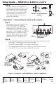
Step 6
Power up the input and output devices.
Distribute power to the mini video switcher
by assembling the external power supply
cable (refer to figure 4) and connecting it
to the power port. Once plugged in, the
switcher automatically turns on. See
“Rear Panel Connections” in the user’s
manual for more details.
Operation — Connecting an input to the output
Step 1
Determine the necessary operation mode
for the MSW (the default is normal).
Choose Autoswitch (press
c
and
e
simultaneously) to automatically switch
to the highest numbered input with active
sync pulses. Choose Normal (press
d
and
e
simultaneously) to manually change
the input. Refer to figure 5 or see “Mode
selection” in the user’s manual for more
information on how to change modes.
Step 2
• If using normal mode, choose the desired input by pressing and releasing its input
button (
b
). The LED (
a
) for the selected input lights.
To switch to a different input, press a different input button.
• If using autoswitch mode, no action is necessary. The mini video switcher
automatically switches to the highest-numbered active input.
68-1267-50
Rev. A
08 09
A/V SWITCHER
MODE NORMAL
AUTO
AUTO
SWITCH
1
2
3
4
2
1
5 4 3
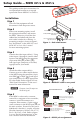
Figure 6 – Example of a typical MSW 4V rs and 4SV rs application
Power Supply
Output Cord
Captive Screw
Connector
3
5
SECTION A–A
Ridges
Smooth
A A
Tie Wrap
Extron
MSW 4SV rs
A/V Switcher
S-VHS VCR
DVD
Projector
Monitor
MSW
4SV rs
P
O
W
E
R
12V
.5A MAX
CONT
ACT
1
2
3
4
A
A
B
1
2
3
4
I
N
P
U
T
S
O
U
T
P
U
T
S
RS-232
Tx
Rx
Extron
MSW 4V rs
A/V Switcher
Camcorder
VCR
VCR
MSW 4V rs
POW
E
R
12V
.5A MA
X
1
2
3
4
C
O
N
TA
C
T
1
2
3
4
A
B
A
B
1
2
3
4
I
N
P
U
T
S
O
U
T
P
U
T
S
R
S-
232
T
x
R
x
Control System
Control System
Figure 4 – Power connector
wiring
Figure 5 – MSW 4SV rs/4V rs
front panel