MSV0804 VGA MATRIX SWITCHER MSV0804 OPERATION MANUAL High Resolution Video Products • A/V System Integration Tools • Interactive Training Systems
Installation and Safety Instructions For Models without a Power Switch: The socket outlet shall be installed near the equipment and shall be accessible. For all Models: No serviceable parts inside the unit. Refer service to a qualified technician. For Models with Internal or External Fuses: For continued protection against fire hazard, replace only with same type and rating of fuse.
Table of Contents Table of Contents ........................................................................................................................................1 Product Overview .......................................................................................................................................2 Description......................................................................................................................................2 Product Features.....................
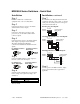
MSV0804 Series Switchers - Quick Start Installation Installation, continued Step 1 Step 7 Install the switcher into a standard 19" equipment rack, or set it on a flat surface. If you will be controlling the matrix with serial commands, cable the control system or computer serial port to the serial port based on the type of connection described below.
MSV0804 Series Switchers - Quick Start, continued Front Panel Controls Functionality, continued Volume buttons adjust the volume of the selected audio output. To store a preset: 1. Configure all necessary input / output patches. 2. Adjust audio volume levels. 3. Press and hold the Preset button for 5 seconds. 4. Press the input or output button you want to use to designate as the preset number for that configuration. Mute button silences the audio output.
2 Product Overview Description MSV0804 is a compact 8 x 4 VGA and stereo audio matrix switcher featuring VGA stereo audio matrix switching, 450 MHz video bandwidth and one switching mode. It is ideal for permanent installations, rentals, complex staging operations and any other display system requiring a high performance, economical VGA stereo audio matrix switcher.
3 Compatibility Video Inputs The MSV0804 matrix switcher provides eight female 15-Pin HD (VGA) inputs and accepts VGA computer video signals on all eight inputs. Audio Inputs Analog Audio Signals Inputs 1-8 include a 5-pin captive screw terminal for analog audio input. All eight analog stereo audio inputs are compatible with unbalanced and balanced line level signals from a VCR, DVD player, computer audio card, or any other audio device that delivers a stereo line level signal.
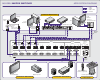
4 Installation Below are instructions for installing the MSV0804 Matrix Switcher. An application diagram showing typical connections is on page 4. Note: Prior to initiating the installation procedure, ensure that there is no power supply cord connected to the unit 1. Place/install the MSV0804 at the desired location. Seat the unit on a flat surface or securely install it in a standard 19" equipment rack using the MTR102 rack ears (provided). The MSV0804 is exactly 2U high without the feet.
APPLICATION DIAGRAM MSV0804 MATRIX SWITCHER = = = = Video Audio Aux. Power Control input devices Local Monitor Laptop PC IN8200 Cable DVD IN1404 Video Scaler DAV101CM Line Driver 3262D Distribution Amplifier DAS101CM Audio Buffer DAS101CM Audio Buffer IN9045 Cable INPUTS AUX POWER PORTS R L R DC OUT 3 L AUDIO DC OUT 4 R L R L R L R L R L R L 2 R L 3 R L SERIAL PORT 4 R L R RS232 RX+ DC OUT 2 1 L TECHNICAL SUPPORT: (800) 882-7117 (714) 921-410 www.inlineinc.
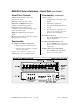
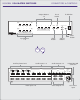
CONNECTORS & CONTROLS MSV0804 VGA MATRIX SWITCHER Preset Button Output Buttons 1-4 1 2 3 4 1 5 6 IR Window 7 2 3 4 BLANK PRESET VOLUME MUTE 8 OUTPUT SELECT INPUT SELECT Rear View Front View Auxiliary Power Ports Audio Inputs 1-8 Audio Outputs 1-4 INPUTS OUTPUTS AUX POWER PORTS AUDIO R L R L R L R L R L R L R L R L 2 R L 3 R L SERIAL PORT 4 R L R RS232 RX+ DC OUT 4 1 L TECHNICAL SUPPORT: (800) 882-7117 (714) 921-410 www.inlineinc.
7 Operation Front Panel Controls Input Select 1 - 8: Selects the designated input. Output Select 1 - 4: Selects the designated output. Preset: Stores or recalls a preset configuration, which includes all input/output patches and volume levels. Blank: Blanks the currently selected output. Mute: Silences audio for the selected output. Volume: Increases or decreases volume level of the selected audio output. IR Window: Receives IR commands from optional CTL 120 IR remote control.
8 To configure a new input/output patch: 1. Press the desired output select button. 2. Press the input select button you want to connect to the output. Example: To patch input 6 to output 2, press the Output 2 button followed by the Input 6 button. To store a preset: 1. Configure all necessary input/output patches. 2. Adjust audio volume levels. 3. Press and hold the Preset button for 5 seconds. 4. Press the input or output button you want to use to designate as the preset number for that configuration.
9 Adjusting input audio volume level Adjusting the volume allows users to equalize the audio levels of the various inputs. This is important so the volume level does not increase/decrease dramatically when switching between inputs. 1. Press and hold the Input button that corresponds to the input device for which you want to adjust the volume. 2. Press the Volume buttons to raise or lower the volume of the input device. The Mute Button silences the audio signal.
10 RS-232/422/485 Connections RS-232 Connection Diagram: Full Duplex RS-422/485 Connection Diagram: Half Duplex RS-485 Connection Diagram: Dipswitch Settings Dipswitch settings change according to the standard used. Higher standards require a different signal type. Dipswitches make subtle adjustments to that signal type. Configure the Dipswitch settings according to the following table. Serial Format RS-232* RS-422/485 Dipswitch Settings 123 OFF 123 ON *Factory default MSV0804 OPERATION MANUAL - v1.
11 Creating Presets Once you create a switch or patch through the Output-Input method, you can assign it a Preset number. This is a valuable, timesaving feature and allows unskilled operators the ability to duplicate complex patches without having to actually configure the patch. To create a preset: 1. Create the desired configuration of input/output connections. 2. Press the Preset button. 3. Press any one of the Input or Output select buttons to pick a storage location for this preset. 4.
12 Remote Operation RS-232 Control The MSV0804 RS-232/RS-422/RS-485 serial control port accepts serial commands from a control system, computer serial port, or any other device capable of sending out serial ASCII commands at compatible baud rates. A complete listing of RS-232/RS-422/RS-485 codes is included below.
13 Using the CTL 120-2 Remote Control CTL 120-2 IR Remote Control sends infrared commands to the CTL101. The CTL101 will convert these IR signals to serial commands so you can control functions on the MSV0804 matrix switcher. A diagram outlining the location and function of each button is provided on page 19. To use the CTL 120-2 remote, press the MATRIX button. The remote is now in matrix switcher mode. To configure a new input/output patch using the CTL 120-2 remote control: 1.
14 Serial Commands All serial commands are applicable to the MSV0502 and MSV0804. Both matrices follow the same command structure with the exception of command strings that designate ii for input assignment and oo for output assignment. For the MSV0502, ii would be 01 – 05 and oo would be 01 – 02, while the MSV0804, ii would be 01 – 08 and oo would be 01 - 04.
15 Set-up Commands These commands are for configuring the switcher, and you only need to send them once. If using a third party control system, you should place most commands in this section in the start-up section of the program. COMMAND [ARC] [CPx@] [CPx?] [CPxbpsfd] [DFLTx] [FPx] [RESx] DESCRIPTION Request for model and version information. Re-sets the communications port to default of 9600, 8, N and 1. • Where x = 1 Query communications port for current settings.
16 Switching Commands These commands can only initiate a one-input-to-one-output switch. COMMAND [MSxOooIii] DESCRIPTION Executes a matrix switch of an input to an output for a specific level. • Where o x = 1 - 3 for specific level o oo = 01 - 04 for output o ii = 00 - 08 for input (00 = blank) Returns the current connections for Level x Blanks a specific output. • Where oo = 01 - 04 for output [MSx?] [BLANKoo] Volume Commands Use these commands to control volume levels for both inputs and outputs.
17 COMMAND [VOLLooxxx] [VOLRoox] [VOLRooxxx] [VOLx] [VOLRMPoox] [VOLSTOP] [VINiix] [VINiixxx] 2002 - INLINE, INC. DESCRIPTION Sets left channel volume level for a specific output. • Where o oo = 01 - 04 for output o xxx = -550 - 090 o Note: 090 equals max (9 db gain), 000 equals factory default (unity gain), -550 equals minimum (-55db) Sets right channel volume level for a specific output.
18 COMMAND [VINx] DESCRIPTION Sets input volume level for all inputs. • Where o x = + (plus sign) to increment input volume o x = - (minus sign) to decrement input volume o x = @ to return input volume to factory default o x = ? to request current volume level Preset Commands The MSV0804 and MSV0502 have the ability to store and recall common configurations. Both units offer 32 presets available via serial control.
19 2002 - INLINE, INC. MSV0804 OPERATION MANUAL - v1.
20 Specifications MSV0804 Video Input Connectors Impedance RGB Level Sync Level Coupling Audio Input Connectors Impedance Level Video Output Connectors Impedance RGB Bandwidth (-3dB) RGB Gain Sync Output Audio Output Audio Connectors Audio Impedance Gain: Frequency Response General RS-232/422/485 Input Port Power: Power Consumption Size Weight Regulatory Compliance Safety EMI 8 Female 15-Pin HD VGA Video: 75 Ohms Sync: High Impedance 0.7 V p-p Nominal 5 V Max. DC coupled.
21 2002 - INLINE, INC. MSV0804 OPERATION MANUAL - v1.
22 Warranty • INLINE warrants the equipment it manufactures to be free from defects in materials and workmanship. • If equipment fails because of such defects and INLINE is notified within three (3) years from the date of shipment, INLINE will, at its option, repair or replace the equipment at its plant, provided that the equipment has not been subjected to mechanical, electrical, or other abuse or modifications.