6 X 3 MATRIX SWITCHER FOR COMPOSITE VIDEO / S-VIDEO AND STEREO AUDIO MSC0603 OPERATION MANUAL High Resolution Video Products • A/V System Integration Tools • Interactive Training Systems
Installation and Safety Instructions For Models without a Power Switch: The socket outlet shall be installed near the equipment and shall be accessible. For all Models: No serviceable parts inside the unit. Refer service to a qualified technician. For Models with Internal or External Fuses: For continued protection against fire hazard, replace only with same type and rating of fuse.
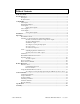
Table of Contents Table of Contents ..........................................................................................................................1 Product Overview .........................................................................................................................2 Description........................................................................................................................2 Product Features...............................................................
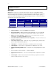
2 Product Overview Description MSC0603 is a compact 6 x 3 composite video/S-Video and Stereo Audio Matrix switcher featuring composite video/S-Video stereo audio matrix switching, 100 MHz video bandwidth, and one switching mode. It is ideal for permanent installations, rentals, complex staging operations, and any other display system requiring a high performance, economical composite video/S-Video stereo audio matrix switcher.
3 Compatibility Video Inputs The MSC0603 matrix switcher provides six female BNC inputs and accepts composite video and S-Video signals on all six inputs. Genlock Input/Output The MSC0603 provides one BNC input and one BNC output for genlock to allow switching to occur during the vertical interval. Audio Inputs Analog Audio Signals Inputs 1-6 include 5-pin captive screw terminals for analog audio input.
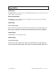
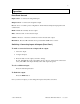
4 Installation Below are instructions for installing the MSC0603 Matrix Switcher. An application diagram showing typical connections is on page 5. Note: Prior to initiating the installation procedure, ensure that there is no power supply cord connected to the unit. 1. Place/install the MSC0603 at the desired location. Seat the unit on a flat surface or securely install it in a standard 19" equipment rack using the MTR102 rack ears (provided). The MSC0603 is exactly 1U high without the feet.
APPLICATION DIAGRAM MSC0603 COMPOSITE/S-VIDEO MATRIX SWITCHER = Video = Audio = Control input devices DVD VCR Video Camera VIDEO IN GEN LOCK Document Camera VIDEO OUT AUDIO IN OUT Y COMP Y COMP Y COMP Y COMP Y COMP Y COMP 1 2 + - IN C 1 C 2 C 3 C 4 C 5 C 6 + R L 3 + + R L 4 + + Plasma Display output devices R L 5 + + R L 6 + + R L Monitor + + Y COMP Y COMP Y COMP R 1 + - C C C L 1 2 3 TECHNICAL SUPPORT (800) 882-7117 (714) 921-4100 w.w.w.
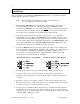
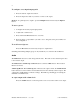
CONNECTORS & CONTROLS MSC0603 COMPOSITE/S-VIDEO MATRIX SWITCHER Input Buttons 1-6 1 2 3 4 Output Buttons 1-3 5 6 1 2 INPUT SELECT MSV0603 A/V Matrix Switcher IR Window Preset Button 3 BLANK PRESET VOLUME OUTPUT SELECT Blank Button Video Inputs 1-6 Video Outputs 1-3 Audio Inputs 1-6 VIDEO IN GEN LOCK RS232/422/485 Serial Port VIDEO OUT AUDIO IN Y COMP Y COMP Y COMP Y COMP Y COMP Y COMP 1 2 + - IN C 1 Genlock Input/Output C 2 C 3 C 4 C 5 C 6 + R L 3 + + R
7 Operation Front Panel Controls Input Select 1 - 6: Selects the designated input Output Select 1 - 3: Selects the designated output Preset: Stores or recalls a preset configuration, which includes all input/output patches and volume levels Blank: Blanks the currently selected output Mute: Silences audio for the selected output Volume: Increases or decreases volume level of the selected audio output IR Window: Receives IR commands from optional CTL 120 IR remote control Switching - Connecting Inputs & Out
8 To configure a new input/output patch: 1. Press the desired output select button. 2. Press the input select button you want to connect to the output. Example: To patch input 4 to output 2, press the Output 2 button followed by the Input 4 button. To store a preset: 1. Configure all necessary input/output patches. 2. Adjust audio volume levels. 3. Press and hold the Preset button for 5 seconds. 4. Press the input or output button you want to use to designate as the preset number for that configuration.
9 Adjusting input audio volume level Adjusting the volume allows users to equalize the audio levels of the various inputs. This is important so the volume level does not increase/decrease dramatically when switching between inputs. 1. Press and hold the Mute button. 2. While still pressing the Mute button, press the Input button that corresponds to the input device for which you want to adjust the volume. 3. Press the Volume buttons to raise or lower the volume of the input device.
10 Dipswitch settings Dipswitch settings change according to the standard used. Higher standards require a different signal type. Dipswitches make subtle adjustments to that signal type. Configure the dipswitch settings according to the following table. Serial Format RS-232* RS-422/RS-485 Dipswitch Settings 123 OFF 123 ON *Factory default Creating Presets Once you create a switch or patch through the Output-Input method, you can assign it a Preset number.
11 Remote Operation RS-232 Control The MSC0603 RS-232/RS-422/RS-485 serial control port accepts serial commands from a control system, computer serial port, or any other device capable of sending out serial ASCII commands at compatible baud rates. A complete listing of RS-232/RS-422/RS-485 codes is included below.
12 Using the CTL120-2 Remote Control CTL120-2 IR Remote Control sends infrared commands to the CTL101. The CTL101 will convert these IR signals to serial commands so you can control functions on the MSC0603 matrix switcher. A diagram outlining the location of each button is on page 18. To use the CTL120-2 remote, press the MATRIX button. The remote is now in matrix switcher mode. To configure a new input/output patch using the CTL120-2 remote control: 1.
13 Serial Commands Addressing Commands If the switcher is being used in RS-232 mode (no other devices connected in parallel) there is no need to assign an address for this unit. If you are using multiple Inline products connected in parallel to a single serial port using RS-422 or RS-485 communications, you will need to assign an address for each unit. The factory default for the unit is no address. The address for the unit must be between 01 and 98.
14 Set-up Commands These commands are for configuring the switcher, and you only need to send them once. If using a third party control system, you should place most commands in this section in the start-up section of the program. COMMAND [ARC] [CPx@] [CPx?] [CPxbpsfd] [DFLTx] [FPx] [RESx] [VISx] DESCRIPTION Request for model and version information. Re-sets the communications port to default of 9600, 8, N and 1. • Where x = 1 Query communications port for current settings.
15 Switching Commands These commands can only initiate a one-input-to-one-output switch. COMMAND [MSxOooIii] [MSx?] [BLANKoo] DESCRIPTION Executes a matrix switch of an input to an output for a specific level. • Where o x = 1 - 3 for specific level o oo = 01 - 03 for output o ii = 00 - 06 for input (00 = blank) Returns the current connections for Level x Blanks a specific output. • Where oo = 01 - 03 for output Volume Commands Use these commands to control volume levels for both inputs and outputs.
16 COMMAND [VOLLooxxx] [VOLRoox] [VOLRooxxx] [VOLx] [VOLRMPoox] [VOLSTOP] [VINiix] [VINiixxx] DESCRIPTION Sets left channel volume level for a specific output. • Where o oo = 01 - 03 for output o xxx = -550 - 090 o Note: 090 equals max (9 db gain), 000 equals factory default (unity gain), -550 equals minimum (-55db) Sets right channel volume level for a specific output.
17 COMMAND [VINx] DESCRIPTION Sets input volume level for all inputs. • Where o x = + (plus sign) to increment input volume o x = - (minus sign) to decrement input volume o x = @ to return input volume to factory default o x = ? to request current volume level Preset Commands The MSC0603 and MSV0804 have the ability to store and recall common configurations. Both units offer 32 presets available via serial control.
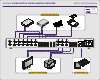
CONNECTORS & CONTROLS CTL120-2 REMOTE CONTROL MSV0502 / MSV0804 / MSC0603 Matrix Switchers MATRIX 1st BUTTON TO PRESS Matrix Button Press this button first to set the CTL120 to control MSV0502 / MSV0804 matrix switchers Numeric Buttons Select desired output, followed by the desired input POWER S VIDEO SCALER SWITCHER MATRIX AUDIO 1 2 3 4 5 6 7 8 9 ENTER 0 PIP INPUT ENT RECALL Vol + Button Increases audio level FREEZE MENU MENU CH + – Enter Button Press to make a menu selection or
19 Specifications MSC0603 Specifications Video Gain Bandwidth Crosstalk Video Input Number/Connectors Nominal Input Level Maximum Input Level Impedance Input Return Loss Video Output Number/Connectors/Signal Type Impedance Output Return Loss Genlock Input Connector Signal Level Output Connector 2002 - INLINE, INC. Unity (1.0 V/V) 100 MHz @ -3dB with .7V p-p input signal, fully loaded 0 - 10 MHz: < +0.1 dB to -0.1 dB 0 - 30 MHz: < +0.3 dB to -0.3 dB 1 MHz: -67.2dB (worst) to -74.
20 MSC0603 Specifications, continued Audio Frequency Response THD+Noise S/N Ratio Output Gain Adjustment Crosstalk Stereo Separation Audio Input Number/Connectors/Signal Type Impedance Maximum Input Level: Input Gain Adjustment Audio Output Number/Connectors/Signal Type Impedance Maximum Output Level Gain Error Control Connector Serial Protocol Baud Rate General Power Supply Shipping Weight Product Weight Dimensions MTBF Storage Temperature/Humidity Ambient Operating Temperature/Humidity Regulatory Approva
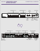
PRODUCT DIMENSIONS MSC0603 VGA MATRIX SWITCHER 11.35" right side view 17.00" 11.35" top view 17.03" 1 2 3 4 5 6 1 2 3 BLANK PRESET VOLUME MUTE 1.78" 1.99" 0.21" INPUT SELECT MSV0603 A/V Matrix Switcher OUTPUT SELECT front view 17.03" 1.99" VIDEO OUT VIDEO IN GEN LOCK AUDIO IN OUT Y COMP Y COMP Y COMP Y COMP Y COMP Y COMP 1 2 + - IN 0.
22 Warranty • INLINE warrants the equipment it manufactures to be free from defects in materials and workmanship. • If equipment fails because of such defects and INLINE is notified within three (3) years from the date of shipment, INLINE will, at its option, repair or replace the equipment at its plant, provided that the equipment has not been subjected to mechanical, electrical, or other abuse or modifications.