
User guide


ES9600 User Guide Chapter 9: Using the GPIO Interface
98 Version 1.13
Chapter 9: Using the GPIO Control Interface
GPIO Physical Interface
WARNING: The GPIO interface provides a 12V DC power output. Ensure that no conductive material is
allowed to come into contact with these terminals.
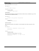
Back view of the ES9600 GPIO Interface:
The GPIO Control Interface offers opto-isolated inputs and relay change-over outputs that can are to be controlled
via third party show-control software or ESCAN (show-control software by Electrosonic).
The Control Interface features:
Four Opto-Isolated inputs that can be configured to provide triggers to either an external show-control
system or the ES9600
Four Digital outputs, each driving low current change-over relays capable of switching up to 1A at
24VDC.
12VDC Power Supply to facilitate the I/O switch functioning.
Opto-Isolated Digital Inputs
The digital input connections consist of a bank of screw terminal connectors with separate 3.5mm removable
terminal blocks for ease of wiring. Each input is assigned two terminals indicated by a ‘+’ and a ‘-‘ symbol.
Because each input is opto-isolated both connections must be used to ensure the correct operation of the input
circuit.
The ES9600 GPIO utilizes four (4) digital input connection channels.
Input Circuit Wiring Configuration
The opto-isolated input circuits provide for various connection scenarios, two common methods follow: