User Guide Matrix Switchers MPX 866 A Media Presentation Matrix Switcher 68-1270-01 Rev.
Safety Instructions • English Warning This symbol is intended to alert the user of important operating and maintenance (servicing) instructions in the literature provided with the equipment. Power sources • This equipment should be operated only from the power source indicated on the product. This equipment is intended to be used with a main power system with a grounded (neutral) conductor. The third (grounding) pin is a safety feature, do not attempt to bypass or disable it.
FCC Class A Notice This equipment has been tested and found to comply with the limits for a Class A digital device, pursuant to part 15 of the FCC Rules. Operation is subject to the following two conditions: 1. This device may not cause harmful interference. 2. This device must accept any interference received, including interference that may cause undesired operation.
Contents Introduction............................................................ 1 About this Guide................................................. 1 About the Media Presentation Matrix Switcher.................................................. 2 Definitions........................................................... 3 Features............................................................... 3 Installation............................................................... 6 Setup and Installation Checklist.....
Matrix Software................................................... 74 Ethernet Connection......................................... 113 Matrix Switchers Control Program...................... 74 Installing the Software................................... 74 Using the Matrix Switcher Control Software... 76 Button-Label Generator Program....................... 94 Using the Button-Label Generator Software....................................................... 95 Ethernet Link...................................
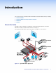
Introduction This section introduces the Extron® MPX 866 A Media Presentation Matrix Switcher, including: zz About this Guide zz About the Media Presentation Matrix Switcher zz Definitions zz Features About this Guide This guide contains installation, configuration, and operating information for the Extron MPX 866 A media presentation matrix switcher (see figure 1). In this guide, the MPX 866 A may be referred to as “the MPX” or “the switcher”.
About the Media Presentation Matrix Switcher A media presentation switcher combines multiple A/V switchers, of different video formats, and a program audio switcher with mute controls in one unit. A matrix switcher distributes any input to any combination of outputs and can route multiple input/output configurations simultaneously.
The switcher is housed in a rack-mountable, 2U high metal enclosure with mounting flanges for standard 19-inch racks. A rack mounting kit is included with the switcher. The switcher has an internal 100 VAC to 240 VAC, 50/60 Hz, 15 watts power supply that provides worldwide power compatibility. Definitions The following terms, which apply to all Extron matrix switchers, are used throughout this guide: Tie — An input-to-output connection Set of ties — An input tied to two or more outputs.
Audio — Input and output balanced or unbalanced stereo audio on 3.5 mm, 5-pole captive screw terminals. Audio input gain/attenuation — Individual input audio levels can be adjusted so there are no noticeable volume differences between sources. Users can set the input level of audio gain or attenuation (-18 dB to +24 dB) via the Ethernet link, RS-232 link, or the front panel.
Global memory presets — 32 global memory presets are a time-saving feature that lets you set up and store input/output configurations in advance. You can then recall those configurations, when needed, with a few simple steps. Rack mounting — Rack mountable in any conventional 19-inch wide rack. Front panel security lockout (Executive mode) — A security lockout feature can be implemented, locking the front panel.
Installation This sections details the installation of the MPX 866 A switchers, including: zz Setup and Installation Checklist zz Rear Panel Cabling and Features zz Front Panel Configuration Port Setup and Installation Checklist Get Ready c Familiarize yourself with the matrix switcher. c Obtain IP setting information for the matrix switcher from the local network administrator. Read “Ethernet Connection”. Perform Physical Installation c If desired, install the switcher in a rack (page 126).
Rear Panel Cabling and Features All switcher connectors are on the rear panel (see figure 2). CAUTIONS: • Use electrostatic discharge (ESD) precautions (be electrically grounded) when making connections. Electrostatic discharge can damage equipment, even if you cannot feel, see, or hear it. • Remove system power before making all connections 1 COMPUTER INPUTS 1 2 3 2 3 5 7 1 4 6 8 2 COMPUTER OUTPUTS 3 5 4 6 9 10 GENLOCK 11 I N P U T S .
Low resolution video group The switcher can connect to up to as many as six S-video sources, composite video sources, or both and output to as many as six video devices. c Video Input 9 and Video Input 10 (composite video inputs) — Connect composite video sources to these female BNC connectors. NOTE: d GENLOCK 9 VIDEO 10 Video Input 9 serves as a timing reference for all other low resolution video group inputs.
Audio input and output By default, the audio ties follow the video ties. Audio breakaway, which can be activated via the optional front panel or under Ethernet or RS-232 control, allows you to select from any one of the audio input sources, regardless of video group, and route it separately from its corresponding video source. See the “Operation” section, the “Programming Guide” section, the “Matrix Software” section, and the “HTML Operation” section for details.
Audio outputs (computer/audio output subgroup only) i Connections for balanced and unbalanced audio outputs — These 5-pole, 3.5 mm captive screw connectors output the selected, unamplified, line level audio. Connect audio devices, such as an audio amplifier or powered speakers. See figure 5 to properly wire an output connector. Use the supplied tie-wrap to strap the audio cable to the extended tail of the connector. NO GROUND HERE. Unbalanced Stereo Output Figure 5.
Serial Ports j RS-232 connectors — Connect one or two host devices, such as computers, touch panel controls, or RS-232 capable PDAs to the switcher via these 3-pole captive screw connectors for serial RS-232 (see figure 6). Use the supplied tie-wrap to strap the serial cable to the extended tail of the connector. RS-232 PRIMARY Tx Rx RS-232 SECONDARY Tx Rx Pin TX RX Gnd Function Transmit data Receive data Signal ground Do not tin the wires! Ground ( ) Receive (Rx) Transmit (Tx) Figure 6.
Ethernet Connection k LAN port — For IP control of the system, connect the matrix switcher to a PC or to an Ethernet LAN via this RJ-45 connector. You can use a PC to control the networked switcher with SIS commands from anywhere in the world. You can also control the switcher from a PC that is running the Extron Matrix Switchers Control Program or has downloaded HTML pages from the Link Activity LED LED switcher.
Reset Button and LED l Reset button — The recessed Reset button initiates four different levels of matrix switcher reset: zz Events (mode 3) reset — Toggles events monitoring on and off. zz IP settings (mode 4) reset — Reset the IP functions of the switcher. NOTE: RESET The IP settings reset does not replace any user-installed firmware. zz Absolute (mode 5) reset — Restore the switcher to the default factory conditions.
Front Panel Configuration Port I/O CONTROL CONFIG ENTER PRESET VIEW ESC VIDEO AUDIO MPX 866 A PRESENTATION MATRIX SWITCHER 14 Figure 8. Front Panel Configuration Port n Configuration port — This 2.5 mm mini stereo jack serves the same serial communications function as the rear panel Remote port, but it is easier to access than the rear port after the matrix switcher has been installed and cabled. The optional 9-pin D to 2.
Operation This section describes the monitoring and operation of the MPX 866 A matrix switcher using the front panel controls and indicators, including: zz Front Panel Controls and Indicators zz Front Panel Operations zz Rear Panel Operations zz Optimizing the Audio zz Troubleshooting zz Configuration Worksheets Front Panel Controls and Indicators The front panel controls (see figure 10) are grouped into two sets. The input and output buttons are on the left side of the control panel.
Input and Output Buttons and LEDs NOTE: See “Front Panel Operations,” later in this chapter for detailed descriptions of all of the following functions and operations. Primary functions Action Press a button: Select an input or output for a tie being created. Indication: Blinking LED: potential tie or untie.
Input buttons and LEDs a Computer inputs 1 through 8 subgroup buttons and LEDs — Select and identify computer video group inputs. b Video inputs 9 through 14 subgroup buttons and LEDs — Select and identify low resolution video group inputs. The video input buttons and LEDs in both groups have one primary function (❏) and two secondary (•) functions: ❏ Select and identify an input. NOTES: • Video outputs in the computer/audio subgroup (b) can only be tied to a computer video subgroup input (a).
Control Buttons and LEDs NOTE: See “Front Panel Operations,” later in this chapter for detailed descriptions of all of the following functions and operations. Primary functions Action Indication: Press: Save changes. Press: Select Preset mode. Press: Select View mode. Press: Cancel/ Escape.
e Enter button and LED — The Enter button and LED have one primary function (❏) and three secondary (•) functions: ❏ Saves configuration or preset changes that you make on the front panel and indicate that a potential change has been created but not saved. To create a simple configuration: • Specify video, audio, or both (see I/O selection buttons and LEDs [i] and [j]) • Press the desired input button (a or b) • Press the desired output button(s) (c or d) • Press the Enter button.
g View (<) button and LED — The View (<) button and LED have one primary function (❏) and four secondary (•) functions: ❏ Selects View-Only mode, which displays the current configuration, and indicates its selection. NOTE: h View-only mode also provides a way to mute and unmute the outputs (see “Muting and Unmuting Video and Audio Outputs” on page 34. • Decrease the audio level of the selected input in Audio mode. • Decrease the volume of the selected output in Audio mode.
I/O Controls NOTE: See “Front Panel Operations,” later in this chapter for detailed descriptions of all of the following functions and operations. You must specify video, audio, or both when you are creating or viewing a configuration. This is done with the Video button (i) and Audio (j) buttons. Primary functions Action Indication: Press: Select video. Press: Select audio. Lit: Video is selected. Lit: Audio is selected.
Input and Output Label Panels k Input and output label panels — These translucent panels can be removed and replaced to insert labels behind the panels. To remove a panel, insert the Phillips-head end of an Extron Tweeker or small Phillips-head screwdriver into the hole in one end of the panel, and gently slide the tab at the edge of the panel out of the recess in the switcher housing.
Front Panel Security Lockouts In the procedural descriptions that follow, it is assumed that the switcher is in Lock mode 0 (fully unlocked). The following two Lock modes are also available: zz Lock mode 1 — All changes are locked from the front panel (except for setting Lock mode 2). Some functions can be viewed. zz Lock mode 2 — Advanced features are locked and can be viewed only. Basic functions, such as tie creation, are unlocked. NOTE: The switcher is shipped from the factory in Lock mode 2.
Creating a Configuration The current configuration can be changed using the front panel buttons. Change the current configuration as follows: 1. Press the Esc button to clear any input LEDs, output LEDs, or control LEDs that may be lit. 2. Select to configure video, audio, or both by pressing the Video button and Audio button. 3. Select the desired input and outputs by pressing the input and output buttons. To indicate potential ties, output LEDs blink when an output is selected but not tied to the input.
Example 1: Creating a set of computer video and audio ties In the following example, input 5 is tied to outputs 3, 4, and 6. The steps show the front panel indications that result from your action. NOTE: This example assumes that there are no ties in the current configuration. 1. Clear all selections: Press and release the Esc button. Press the Esc button to clear all selections. CONTROL The LED blinks once. ENTER PRESET VIEW ESC 2.
The current configuration is now input 5 video and audio tied to output 3, output 4, and output 6 (see figure 12). Input 5 3 4 Output 6 Video Audio Figure 12. Example 1, final configuration Example 2: Adding a tie to a set of computer video and audio ties In the following example, a new video tie is added to the current configuration. The steps show the front panel indications that result from your action. NOTE: This example assumes that you have performed example 1. 1.
5. Confirm the change: Press and release the Enter button. Press the Enter button to confirm the configuration change. ENTER The Enter LED and all input LEDs and output LEDs return to the unlit state. The current configuration (see figure 13) is now: zz Input 5 video tied to output 1, output 3, output 4, and output 6 zz Input 5 audio tied to output 3, output 4, and output 6 Input 5 1 3 4 Output 6 Video Audio Figure 13.
4. Select the output: Press and release the output 4 button. Press and release the Computer/Audio Output 4 button. The LED blinks to indicate that the selected computer video input will be untied. ENTER 1 2 3 4 5 6 COMPUTER/AUDIO OUTPUTS PRESET The Enter LED blinks to indicate the need to confirm the change. 5. Confirm the change: Press and release the Enter button. Press the Enter button to confirm the configuration change.
Example 4: Creating a set of low resolution video and audio ties NOTE: This example shows the unusual indications that happen when you make video and audio ties in the low resolution video group. In the following example, low resolution input 12 is tied to outputs 7 and 8. The steps show the front panel indications that result from your action. NOTES: • This example does not build on examples 1, 2, and 3. It assumes that there are no ties in the current configuration.
4. Select the output: Press and release the low resolution Output 7 and Output 8 buttons. NOTE: The entire set of ties can be canceled at this point by pressing and releasing the Esc button. The Esc LED flashes once. Press and release the Video Output 7 and Output 8 buttons. The Output 7 and Output 8 buttons blink to indicate that the selected low resolution video input will be tied to these outputs.
Viewing a Configuration The current configuration can be viewed using the front panel buttons and LEDs. The View-only mode prevents inadvertent changes to the current configuration. View-only mode also provides a way to mute video and audio outputs (see “Muting and Unmuting Video and Audio Outputs” on page 34. View the current configuration as follows: 1. Press the Esc button to clear any input LEDs, output LEDs, or control button LEDs that are lit. 2. Press and release the View button.
Example 5: Viewing video and audio, audio only, and video only ties The following example shows the viewing of the video and audio, audio-only, and video-only ties in the current configuration. The steps show the front panel indications that result from your action. NOTE: This example assumes that you have performed example 1, example 2, and example 3. 1. Clear all selections: Press and release the Esc button. The button flashes once. 2. Select View-only mode: Press and release the View button.
5. Deselect video: Press and release the Video button. I/O The output buttons for outputs that are tied to input 5 light to indicate audio ties (audio breakaway). VIDEO AUDIO Press the Video The Audio LED remains button to delesect it. lit to indicate that only The LED is unlit audio is selected. when deselected. 1 2 3 4 5 6 COMPUTER/AUDIO OUTPUTS The output buttons for audio outputs that are not tied to input 5 are unlit. 6.
Muting and Unmuting Video and Audio Outputs NOTE: Mutes are protected when front panel Lock mode 2 is selected. You can view the mute status in Lock mode 2 but you cannot adjust it from the front panel (see “Setting the Front Panel Locks (Executive Modes)” on page 47). Individual video and outputs can be muted or unmuted as follows: 1. Press the Esc button to clear any input LEDs, output LEDs, or control LEDs that may be lit. 2. Press and release the View button. 3.
Example 6: Muting and unmuting an output In the following example, several switcher outputs are muted and unmuted. The steps show the front panel indications that result from your action. 1. Clear all selections: Press and release the Esc button. The button flashes once. 2. Select View-only mode: Press and release the View button. The View button lights red. 3. Select either video or audio for viewing: Press and release the Video button and the Audio button.
5. Unmute the outputs: One at a time, press and hold the Output 3 button and then the Output 4 buttons for approximately 2 seconds until each LED lights steadily. The output 3 and output 4 signals are unmuted. Press and hold the Computer/Audio Output 3 and Computer Output 4 button. 2 3 4 5 COMPUTER/AUDIO OUTPUTS 2 seconds 2 3 4 5 COMPUTER/AUDIO OUTPUTS The LEDs stop blinking and light to indicate that the computer video outputs are unmuted. Release the button. 6.
Example 7: Saving a global preset In the following example, the current configuration is saved as a preset. The steps show the front panel indications that result from your action. 1. Clear all selections: Press and release the Esc button. The button flashes once. 2. Select Save Preset mode: Press and hold the Preset button for approximately 2 seconds until it blinks. Press and hold the Preset button until the Preset LED blinks. All input and output LEDs with assigned presets light.
Example 8: Recalling a global preset In the following example, a preset is recalled to become the current configuration. The steps show the front panel indications that result from your action. 1. Clear all selections: Press and release the Esc button. The button flashes once. 2. Select Recall Preset mode: Press and release the Preset button. Press and release Preset button. The Preset LED lights. PRESET All input and output LEDs with assigned presets light.
Selecting Composite Video or S-video Low resolution video inputs 11 through 14 are individually configurable as either composite video or S-video. View and change this variable from the front panel as follows: NOTE: Video format is protected when front panel Lock mode 2 is selected. You can view the format in Lock mode 2 but you cannot adjust it from the front panel. (see “Setting the Front Panel Locks (Executive Modes)” on page 47). 1.
NOTE: Video format is protected when front panel Lock mode 2 is selected. You can view the format in Lock mode 2 but you cannot change it from the front panel (see “Setting the Front Panel Locks (Executive Modes)” on page 47). If front panel Lock mode 2 is selected and you try to perform step 4, the actions are ignored and the Enter, Video, and Audio buttons flash. 4. Change the format: Press and release the Video Output button, 7 or 8, for the desired format.
Viewing and Adjusting the Input Audio Level The audio level of each input can be displayed and adjusted through a range of -18 dB to +24 dB to ensure that there is no noticeable volume difference among sources (see figure 16). The audio level can be adjusted from the front panel or under RS-232 or Ethernet control.
Input Audio Level Adjustment Displays 1. Press the Esc button to clear any input LEDs, output LEDs, or control LEDs that are Output LED View Esc lit. dB 1 2 3 4 5 6 7 8 dB 2. To enter Audio mode, press and hold the Audio button until the Audio LED begins to blink, then release the button. +24 3. Press and release an input button to select an input. The output LEDs display the audio level for the selected input.
Example 10: Viewing and adjusting an input audio level In the following example, an audio level is viewed and adjusted. The steps show the front panel indications that result from your action. 1. Clear all selections: Press and release the Esc button. The button flashes once. 2. Enter Audio mode: Simultaneously press and hold the Audio button. Press and hold the Audio button. I/O 2 seconds AUDIO AUDIO The LED blinks to indicate Audio mode. Release the button. 3.
5. Exit the Audio mode: Press and release the Audio button. Press the Audio button to exit audio mode. I/O All input LEDs and output LEDs return to the unlit state. VIDEO AUDIO The Audio LED stops blinking and lights steadily. The Video button lights. Viewing and Adjusting the Output Volume The audio level of each output can be displayed and adjusted through a range of 100% (no attenuation) to 0% (maximum [76 dB] attenuation).
See the table at right to read the volume display. The input LEDs light sequentially to indicate the approximate volume of the selected output. Volume is defined as a percentage of the input audio signal that is applied to the output. From 0% of volume, the first Esc (>) button push applies 5.5% of the input audio signal and the Input 1 LED begins to blink slowly. From 5.5% on, each Esc (>) push applies 1.5% more of the input audio signal to the output: zz zz zz Push Esc (>) button — 5.5% + 1.
Example 11: Viewing and adjusting an output volume level In the following example, the audio output volume is viewed and adjusted. The steps show the front panel indications that result from your actions. See the table on page 45 to read the volume display. 1. Clear all selections: Press and release the Esc button. The button flashes once. 2. Enter Audio mode: Simultaneously press and hold the Audio button. Press and hold the Audio button. I/O 2 seconds AUDIO AUDIO The LED blinks to indicate Audio mode.
Press the Esc button to decrease the audio attenuation (thereby increasing the audio level) that is applied to the output volume level by 1 dB per button push. The input LEDs, independent of video group, display the selected output's audio volume level. In this example, the lit input buttons indicate 56.5 to 62.5 percent of the applied audio input. The unlit input buttons indicate an audio volume attenuation of 25 dB to 29 dB.
Selecting Lock mode 2 or toggling between mode 2 and mode 0 NOTES: • If the switcher is in Lock mode 0 or mode 1, this procedure selects mode 2. • If the switcher is in Lock mode 2, this procedure selects mode 0 (unlocks the switcher). To toggle the lock on and off, press and hold the Enter button, the Video button, and the Audio button for approximately 2 seconds (see figure 19).
Performing a System Reset from the Front Panel The front panel reset is identical to the EZXXX} SIS command described in the Programming Guide section. A system reset: zz Clears all ties and presets zz Clears all video and audio mutes zz Sets all input audio levels to unity gain (+0 dB) zz Sets all output volume levels to 100% (0 dB of attenuation).
Selecting the Baud Rate of the RS-232 Primary Port The matrix switcher supports the RS-232 serial communication protocol on the font panel Configuration port and the rear panel RS-232 Primary and RS-232 Secondary ports. All three ports can operate at 9600, 19200, 38400, and 115200 baud rates. The baud rate for the primary port is variable can be viewed and changed from the front panel. NOTE: Baud rate is protected when front panel Lock mode 2 is selected.
Rear Panel Operations The rear panel has a Reset button that initiates four levels of resets (identified as modes 1, 3, 4, and 5 for the sake of comparison with an Extron IPL product). The Reset button is recessed, so use a pointed stylus, ballpoint pen, or small screwdriver to access it. For different reset levels, press and hold the button while the switcher is running or press and hold the button while you apply power to the switcher. See the following table for a summary of the modes.
Performing Soft System Resets (Modes 3, 4, and 5) Perform a soft reset of the switcher as follows: 1. Use an Extron Tweeker or other small screwdriver to press and hold the rear panel Reset button (see figure 22) until the rear panel Reset LED and the front panel Preset and View buttons blink once (events reset), twice (IP settings reset), or three times (absolute reset). 2. Release the Reset button and then immediately press and release the Reset button again.
Performing a Hard Reset The hard reset function restores the switcher to the base firmware that it shipped with. After a hard reset, events do not automatically start, but user settings and files are restored. Perform a hard reset as follows: NOTE: The hard reset restores the factory-installed firmware. The switcher reverts to that factory firmware the next time power is cycled off and on unless a firmware update is performed before the power cycle. 1. If necessary, turn off power to the switcher. 2.
Troubleshooting This section gives recommendations on what to do if you have problems operating the switcher. 1. Ensure that all devices are plugged in and powered on. The switcher is receiving power if any of the front panel button indicators are lit. 2. Check to see if one or more outputs are muted. 3. Ensure an active input is selected for output on the switcher. 4. Ensure that the proper signal format is supplied. 5. Check the cabling and make corrections as necessary. 6.
Worksheet Example 2: Daily Configuration Figure 25 continues from worksheet example 1 by showing the video and audio ties that make up the configuration of preset 1. A solid ink line shows video ties and a red pencil lines show the audio ties.
Worksheet Example 3: Test Configuration The A/V system in our fictional organization needs to be fine tuned on a regular basis. Figure 26 shows a typical test configuration, with an Extron video test generator (inputs 8 and 13) connected to each video group. Each VTG generates a test pattern of the appropriate resolution to all connected outputs. Sound checks are run from the CD player (input 14) to two output devices that accept audio; the VCR (output 6) receives no audio in this configuration.
MPX 866 A Media Presentation Matrix Switcher • Operation 57 2 1 3 3 4 4 5 5 6 6 Title: Video: 7 Blank Configuration Worksheet 8 Audio: Fill in the preset number and use colors, or dashes, etc. to make connecting lines. Indicate if the configuration is for video, audio, or both.
Programming Guide This section describes the operation of the MPX 866 A switcher using the Simple Instruction Set, including: zz RS-232 Ports zz Ethernet (LAN) Port zz Host-to-Switcher Instructions zz Switcher-Initiated Messages zz Switcher Error Responses zz Using the Command and Response Tables zz Special Characters RS-232 Ports The switcher has three serial ports that make serial control of the switcher possible.
Rear Panel Remote Ports RS-232 PRIMARY Tx Rx RS-232 SECONDARY Tx Rx Pin TX RX Gnd Function Transmit data Receive data Signal ground Controlling Device Do not tin the wires! Ground ( ) Receive (Rx) Transmit (Tx) Bidirectional Ground ( ) Receive (Rx) Transmit (Tx) Figure 27. Remote Connector Pin Assignments Front Panel Configuration Port NOTE: This port parallels the rear panel RS-232 Secondary port.
Ethernet (LAN) Port The rear panel Ethernet connector on the switcher can be connected to an Ethernet LAN or WAN. Communications between the switcher and the controlling device are via Telnet (a TCP socket using port 23). The TCP port can be changed if necessary, via SIS. This connection makes SIS control of the switcher possible using a computer connected to the same LAN or WAN.
Establishing a Connection Establish a network connection to a MPX 866 A switcher as follows: 1. Open a TCP socket using the IP address of the switcher. NOTE: If the local system administrators have not changed the value, the factoryspecified default, 192.168.254.254, is the correct value for this field. The switcher responds with a copyright message including the date, the name of the product, firmware version, part number, and the current date/time.
Host-to-Switcher Instructions The switcher accepts SIS commands through the RS-232 ports and Ethernet port. SIS commands consist of one or more characters per field. No special characters are required to begin or end a command character sequence. When a command is valid, the unit executes the command and sends a response to the host device. All responses from the unit to the host end with a carriage return and a line feed (CR/LF = ]), which signals the end of the response character string.
OutnnVolxx] The switcher initiates the Vol message when a front panel output audio volume change has occurred. nn is the input number and xx is the volume level. Vmtnn•x] The switcher initiates the Vmt message when a video output mute is toggled on or off from the front panel. “nn” is the output number, • is a space, and “x” is the mute status: 1 = on, 0 = off. Amtnn*x] The switcher initiates the Amt message when an audio or RS-232 output mute is toggled on or off from the front panel.
Command and Response Table for SIS Commands Symbol Definitions ] } = CR/LF (carriage return/line feed) (hex 0D 0A) = Carriage return (no line feed, hex 0D) | = Pipe (can be used interchangeably with the } character) • = Space character E = Escape key (hex 1B) NOTE: A video input from either of the two groups cannot be tied to an output in the other group. Audio can be tied to any output, regardless of the video group to which it was input.
Command and Response Table for SIS Commands Command ASCII Command Response (Host to Unit) (Unit to Host) Additional description Create ties NOTES: • The ! tie command for RGB and % tie command for video can be used interchangeably for ties within the same group. • Video ties cannot be made between the computer video group and the low resolution video group.
Command/Response Table for SIS Commands (continued) Command ASCII Command Response (Host to Unit) (Unit to Host) Additional description Create ties (continued) NOTES: • All video and audio group rules apply to all of the tie all commands listed below. • The ! tie all command for RGB and % tie all command for video can be used interchangeably for ties within the same group.
Command/Response Table for SIS Commands (continued) Command ASCII Command Response (Host to Unit) (Unit to Host) Additional description Audio output volume NOTE: The table below the commands defines the value of each audio volume step.
Command/Response Table for SIS Commands (continued) Command ASCII Command Response (Host to Unit) (Unit to Host) Additional description Audio input gain and attenuation NOTE: The set gain (G) and set attenuation (g) commands are case sensitive. Set input audio gain to +dB value Example: Set input audio attenuation to -dB value Increment gain Example: Decrement gain Example: Read input gain X#*X*G InX#•AudX&] 1*2G In01•Aud+02] InX#•AudX&] Set input 1 audio gain to +2 dB.
Command/Response Table for SIS Commands (continued) Command ASCII Command Response (Host to Unit) (Unit to Host) EX1),X1@NG} NmgX1),X1@] E1,Security 1NG} Nmg01,Security 1] Additional description Preset names Write global preset name Example: Read global preset name Example: EX1)NG} Name global preset 1 “Security 1”. X1@] Security 2] E2NG} View ties, gain, volume, mutes, and presets NOTES: • The ! read tie command for RGB and the % read tie command for video can be used interchangeably.
Command/Response Table for SIS Commands (continued) Command ASCII Command Response (Host to Unit) (Unit to Host) Additional description View ties, gain, volume, mutes, and presets (continued) View audio global preset configuration Command description: Response description: Example: EX1)*X@*2VC} X!1•X!2• ... •X!16•Aud] Show the audio configuration for preset X1). Show the input tied to 16 sequential outputs, starting from output X!. (Audio outputs 7 through 16 do not exist on this switcher model.
Command/Response Table for SIS Commands (continued) Command ASCII Command Response (Host to Unit) (Unit to Host) Additional description Lock (executive) modes NOTE: See “Setting the Front Panel Locks (Executive Modes)” in the Operation section for more information on the Lock modes. 1X 2X Exe1] Exe2] Enable Lock mode 1. Enable Lock mode 2. 0X Exe0] Enable Lock mode 0.
Command and Response Table for IP-Specific SIS Commands Symbol definitions X2! = Web page priority 0 = internal 1 = user X2@ = Matrix name (Up to 240 alphanumeric characters) NOTE: The following characters are invalid or not recommended in the name: {space} + ~ , @ = ` [ ] { } < > ‘ “ ” ; : | \ and ?.
Command and Response Table for IP-Specific SIS Commands Command ASCII Command Response (Host to Unit) (Unit to Host) Set Web page priority Read Web page priority Set matrix name (location) Read matrix name (location) Reset matrix name to factory default Set time and date Read time and date Set GMT offset EX2!Cpag} ECpag} EX2@CN} ECN} E•CN} IwpX2!] EX2$CT} ECT} EX2^CZ} IptX2$] X2%] IpzX2^] Read GMT offset ECZ} EX2&CX} X2^] IpxX2&] Additional description IP setup commands Set Daylight Savings T
Matrix Software This section introduces the Extron Matrix Switchers Control Program software that is included with the MPX 866 A Media Presentation Matrix Switcher switchers, including: zz Matrix Switchers Control Program zz Button Label Generator Matrix Switchers Control Program The Matrix Switchers Control Program communicates with the switcher via the Ethernet LAN port or either serial port to provide an easy way to set up ties and sets of ties.
2. Click the Software tab (see figure 30). 3. Scroll to the desired program and click Install (see figure 31). Figure 31. Software Installation 4. Follow the on-screen instructions.
Using the Matrix Switcher Control Software Many items found in the Matrix Switchers Control Program are also accessible front panel controls (see the“Operation” section) and under SIS control (see the “Programming Guide“ section). The Matrix Switcher + Help Program provides information on settings and on how to use the control program, itself. 1. To run the Matrix Switchers Control Program, click Start > Programs > Extron Electronics > Matrix Switchers > MATRIX Switcher + Control Pgm.
3. If you selected IP [LAN] in step 2, the IP Connection dialog box appears (see figure 33). Figure 33. Address and Password Entry a. Examine the Matrix IP Address field in the IP Connection window. The field displays the last Extron IP address entered. If the IP address is correct, proceed to step 3b. If the address is not correct, either click in the Extron IP Address field and enter the IP address or click the scroll down button ( ) and select from among the recently used addresses. Proceed to step 3b.
Figure 34. Extron Matrix Switchers Control Program Window (Blank) Figure 35.
4. � To create a tie, drag an input box to one or more output boxes. To remove a tie, drag the output box to its tied input box or to the trash can. zz To make the control program easier to use, assign a device icon to each input and output. Click on a box that represents an input or output, and drag the desired icon onto the box from the icon palette that appears.
Valid addresses consist of four 1-, 2-, or 3-digit numeric subfields, properly called “octets,” separated by dots (periods). Each field can be numbered from 000 through 255. Leading zeroes, up to three digits total per field, are optional. Values of 256 and above are invalid. The default addresses are as follows, but if these conflict with other equipment at your installation, you can change the addresses to any valid value: � IP address 192.168.254.254 zz Subnet mask 255.255.0.0 � Gateway address 0.
Date, Time (local), and GMT (offset) fields The Date field displays the current date in the Greenwich Mean Time zone. The Time (local) field displays the current time in the local time zone. The GMT field displays the amount of time, in hours and minutes, that the local time varies from the GMT international time reference. NOTE: Rather than the following procedure, you can click the Sync Time to PC button to set the switcher to the internal time of your computer.
Administrator Password and User Password fields The Administrator Password field displays the password required to log on to the matrix switcher via the Ethernet port with all of the rights and privileges of an administrator. The User Password field displays the password required to log on to the matrix switcher via the Ethernet port as a user, without all of the rights and privileges of an administrator. Passwords are case sensitive and are limited to 12 upper-case and lower-case alphanumeric characters.
Updating firmware The firmware upgrade utility provides a way to replace the firmware that is coded on the control board of the switcher without taking the switcher out of service. Update the switcher firmware as follows: 1. Visit the Extron website, www.extron.com, click the Download tab, and then click the Firmware link (see figure 37). NOTE: 1 The version, release date, and size shown are sample values only. 1 2 3 3 Figure 37. Location of Firmware Upgrade Files 2.
NOTE: The version shown is a sample values only. 4 4 5 Folder where firmware is installed 6 Figure 38. Downloading Firmware Upgrade Files 7. Connect a computer that runs the Windows operating system to either switcher serial port or the switcher LAN port. See “Installation” for more details.
8. Start the Matrix Switchers Control Program and connect to the matrix switcher. See “Using the Matrix Switcher Control Software,” steps 1 through 4, starting on page 76. 9. Click Tools > Update firmware. zz If the switcher is connected via the LAN port, the Select Files dialog box appears (see figure 39). See Ethernet-connected firmware upload, below.
Serial-port-connected firmware upload 10 Figure 40. Extron Firmware Loader Window 10. Select the MPX 866 A matrix switcher and click File > Open. The Choose Firmware File screen appears (see figure 41). 11 11 Figure 41. Choose Firmware File Window 11. Navigate to and select the new firmware file. Click Open. The Choose Firmware File window closes. CAUTION: NOTE: The firmware file must have an .s19 extension. Other file types can cause the switcher to stop functioning.
Uploading HTML files You can create customized HTML pages for the switcher to display. The HTML Files List window (see figure 43), accessible via the Tools menu, provides a way to view the contents of the file system of the switcher and upload custom HTML pages to the switcher. 4 7 8 Figure 43. HTML Files List Window Upload HTML pages as follows: NOTES: • The files listed in figure 43 are shown for example only and may not be present on your switcher.
Windows Buttons, Drop Boxes, and trash can The buttons, drop boxes, and trash can on the right side of the Matrix Switchers Control Program window perform the following functions: Power — Unavailable for MPX 866 A switchers, because the switcher power cannot be controlled via software. Executive Mode — Allows you to lock out front panel operations, except for the view-only mode functions.
Tools menu Assign Device Icons — Displays the complete set of input and output device icons. You can drag any of these icons to the input and output boxes. Edit Device Palette — Allows you to add your own device icon graphics. Audio-Input gain settings — Displays the audio gain level setting for a single input or for all inputs and allows you to change it (see figure 44).
Update Firmware — Allows you to replace the firmware .without taking the switcher out of service (see “Updating Firmware”). IP Options — Allows you to set IP options (see “IP Settings/Options Window”). HTML file manager — Displays a list of HTML files installed on the switcher and allows you to upload custom files from a connected PC to the switcher. See “Uploading HTML Files” on page 87.
Audio Input Configuration selection Displays the Configure Audio Options window, which allows you to make audio input gain and attenuation adjustments to all inputs, either individually or all at once, from one window (see figure 48). Figure 48. Configure Audio Options Dialog Box Preferences menu Immediate Changes — Causes configuration changes to take effect immediately. Hold/verify Changes — Delays implementation of configuration changes until the Changes – Take button is pressed.
Ties as Crosspoints — Displays ties as a matrix of inputs and outputs (see figure 50). Ties that have been made are indicated as amber or green boxes. Ties that will take effect when you click the Take button are indicated by +. Ties that will be broken when you click the Take button are indicated by –. Figure 50.
Master-Reset selection Master reset performs all of the following functions: zz zz zz zz zz Clears all ties Clears all presets Clears all video and audio mutes Sets all input audio levels to unity gain (0 dB) Sets all output volume levels to 100% (0 dB of attenuation) NOTE: Master reset does not reset the Internet protocol (IP) settings. Using Emulation Mode Emulation mode allows you to set up the software without connecting the switcher. Use emulation mode as follows: 1.
Using the Help system For information about program features, you can access the help program in any of the following ways: zz From the Extron Electronics program folder or group, double-click the MATRIX Switcher Help icon (shown at right). zz From within the Matrix Switchers Control Program, click Help > Contents on the menu bar. zz From within the Matrix Switchers Control Program, press the keyboard key.
Using the Button-Label Generator Software 1. To run the Button-Label Generator program, click Start > Programs > Extron Electronics > Button Label Generator > Button Label Generator. The Button-Label Generator window appears (see figure 53). Figure 53. Extron Button-Label Generator Window 2. In the Systems selection box, choose the CP 300 1616 Series option to match the label strip size for your MPX 866 switcher. NOTE: You will need to trim excess label positions with scissors. 3.
HTML Operation This section describes the operation of the MPX 866 A matrix switcher, including: zz Opening the Embedded Web Pages zz Status Tab zz Configuration Tab zz File Management Tab zz Control Tab zz Special Characters The switcher can be controlled and operated through its LAN port, connected via a LAN or WAN, using a web browser such as Microsoft® Internet Explorer®. The browser display of the status or operation of the switcher has the appearance of web pages.
4. Press the keyboard key. The switcher checks to see if it is password protected. If the switcher is not password protected, it checks and downloads the HTML pages (proceed to step 7). If the switcher is password protected, the switcher downloads the Enter Network Password page (see figure 54). Figure 54. Enter Network Password Page NOTE: A User name entry is not required. 5. Click in the Password field and type in the appropriate administrator or user password. Click the OK button. 6.
Status Tab System Status Page The System Status page (see figure 55) provides an overall view of the status of the matrix switcher, including individual voltages, power supply status, and fan status. The System Status page is the default page that the switcher downloads when you connect to the switcher. Access the System Status page from other pages by clicking the Status tab. Refresh Figure 55.
Configuration Tab System Settings Page The MPX 866 A matrix switcher downloads the System Settings page (see figure 56) when you click the Configuration tab. The screen consists of fields in which you can view and edit IP administration and system settings. You can access the Passwords pages by clicking the appropriate link. See “Ethernet Connection” for basic information about IP addresses and subnetting. Refresh Video Input Settings Select Passwords Select Firmware Upgrade Figure 56.
DHCP radio buttons The DHCP On radio button directs the switcher to ignore any entered IP addresses and to obtain its IP address from a Dynamic Host Configuration Protocol (DHCP) server (if the network is DHCP capable). The DHCP Off radio button turns DHCP off. Contact the local system administrator to determine if DHCP is appropriate. NOTE: When you change DHCP from on to off, the IP address of the switcher resets to its default value, 192.168.254.254.
Date/Time Settings fields The Date/Time Settings fields (see figure 57) provide a location for viewing and setting the time functions. Figure 57. Date/Time Settings Fields Change the date and time settings as follows: 1. Click the drop box for variable to be changed. The adjustable variables are month, day, year, hours, minutes, AM/PM, and (time) zone. A drop-down scroll box appears (the year drop box is selected in figure 57). 2.
Video Input Settings Page Access the Video Input Settings page (figure 58) by clicking the Video Input Settings link on the System Settings page. Low resolution video inputs 11 through 14 are individually configurable as either composite video or S-video. View and change this variable by clicking in the desired radio button for the input that needs to be changed. System Settings Refresh Select Passwords Select Firmware Upgrade Figure 58.
NOTE: An administrator password must be created before a user password can be created. To clear an existing password so that no password is required, enter a single space character in the Password and Re-enter Password fields, and click the Submit button. Firmware Upgrade Page The Firmware Upgrade page provides a way to replace the firmware that is coded on the control board of the switcher without taking the switcher out of service.
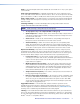
7 10 8 9 Figure 61. Firmware Upgrade 7. Click the Browse button. A Choose File to Upload window appears. 8. Navigate to the folder where you saved the firmware upgrade file. Select the file. NOTES: • Valid firmware files must have the file extension “.S19.” A file with any other extension is not a firmware upgrade. • The original factory-installed firmware is permanently available on the MPX 866 A matrix switcher.
File Management Tab File Management Page To delete files such as HTML pages from the switcher or to upload your own files to the switcher, click the File Management tab. The switcher downloads the File Management HTML page (see figure 62). Figure 62. File Management Page NOTE: The files listed in figure 62 are shown for example only and may not be present on your switcher. To delete a file, click the Delete button associated with that file.
Control Tab Set and View Ties Page You can create ties on the Set and View Ties page (see figure 63). Access the Set and View Ties page by clicking the Control tab. Refresh Video & Audio Settings Global Presets Figure 63. Set and View Ties Page The page consists of a matrix of input (rows) and output (columns) selection buttons of four different colors: zz The amber buttons indicate video and audio ties. zz The green buttons indicate video only ties. zz The red buttons indicate audio only ties.
NOTES: • Video ties can only be made within the following groups, never between the groups: • • The computer video group (inputs 1 through 8 and outputs 1 through 6) The low resolution video group (inputs 9 through 14 and outputs 7 through 12) • Audio can be tied only to outputs 1 through 6. If you make a video and audio tie from the low resolution video group (inputs 9 through 14), audio is automatically redirected to tie it and output in the computer subgroup (outputs 1 through 6).
RGB and Audio Settings Page The RGB and Audio Settings page provides a way to set the input audio gain and attenuation, set the output volume, and mute and unmute all video and audio outputs. Access the RGB and Audio Settings page (see figure 64) by clicking the RGB & Audio Settings link on the Control page. Set & View Ties Refresh Global Presets Figure 64.
3. Click the Input Audio Level (dB) drop box. A drop down scroll box appears (see figure 65). Figure 65. Gain Drop Box 4. Click and drag the slider or click the scroll up the desired audio level is visible. button or scroll down button until 5. Click the desired gain or attenuation value. Mute and unmute one or all outputs Mute one or all outputs as follows: 1. To select an individual output to mute or unmute, click the Output drop box. A drop down scroll box appears (see figure 66). Figure 66.
Change the output volume level Users can set the volume level for each output through a range of zero steps of attenuation (full attenuation, minimum volume) to 64 steps of attenuation (no attenuation, full volume) from the RGB and Audio Settings page. Change an audio level setting as follows: 1. Click the output drop box. A drop down scroll box appears. 2. Click the desired output. 3. Click the Volume Steps (64 Max) drop box. A drop down scroll box appears (see figure 67). Figure 67. Volume Drop Box 4.
Global Presets Page You can save and recall global presets from the Global presets page (see figure 68). Access the Global presets page by clicking the Global Presets link on the left of the Control page. Set and View Ties Video & Audio Settings Refresh Figure 68. Global Presets Page Saving a preset Save the current configuration (configuration 0) as a preset as follows: 1. Click the Save Preset button. 2. Select the desired preset by clicking on one of the presets listed.
Special Characters The HTML language reserves certain characters for specific functions. The switcher does not accept these characters as part of preset names, the name of the switcher, passwords, or locally created file names. The switcher rejects the following characters or they are not recommended: {space} + ~ , @ = ‘ [ ] { } < > ’ “ “ ; (semicolon) : (colon) | \ and ?.
Ethernet Connection This section provides a high level discussion of the Ethernet connection to the switcher and a primer on the subject of subnetting. Topics that are covered, include: zz Ethernet Link zz Subnetting — A Primer Ethernet Link The rear panel Ethernet connector on the MPX 866 A matrix switcher can be connected to an Ethernet LAN or WAN. This connection makes SIS control of the switcher possible using a computer connected to the same LAN.
Default IP Address To access the MPX 866 A matrix switcher via the LAN port, you need the IP address of the switcher. If the address has been changed to an address comprised of words and characters, you can determine the actual numeric IP address using the ping utility. If the address has not been changed, the factory-specified default is 192.168.254.254. Ping can also be used to test the Ethernet link to the MPX 866 A matrix switcher.
Configuring the MPX 866 A Matrix Switcher for Network Use via the ARP Command The ARP (address resolution protocol) command tells your computer to associate the MAC (media access control) address of the MPX 866 A matrix switcher with the assigned IP address. You must then use the ping utility to access the controller, at which point the IP address of the controller is reconfigured. Use ARP to configure the IP address as follows: 1.
6. After verifying that the IP address change was successful, enter and issue the arp –d command at the Command prompt. For example: arp –d 10.13.197.7 removes 10.13.197.7 from the ARP table or arp –d* removes all static IP addresses from the ARP table. Connecting as a Telnet Client The Microsoft Telnet utility is available from the Command prompt. Telnet allows you to input SIS commands to the MPX 866 A matrix switcher from the PC via the Ethernet link and the LAN.
Telnet Tips It is not the intention of this guide to detail all of the operations and functionality of Telnet; however, some basic level of understanding is necessary for operating the MPX 866 A matrix switcher via Telnet. Open Connect to the MPX 866 A matrix switcher using the Open command. Once you are connected to the switcher, you can enter the SIS commands the same as you would if you were using the RS-232 of RS-422 link. Connect to the MPX 866 A matrix switcher as follows: 1.
Set carriage return-line feed Unless commanded otherwise, Telnet transmits a line feed character only (no carriage return) to the connected switcher when you press the key. This is the correct setting for SIS communication with the switcher. The Telnet set crlf command forces Telnet to transmit carriage return and line feed characters when is pressed, but if crlf is set, the SIS link with the switcher does not function properly.
Subnet Masks and Octets The subnet mask (see figure 74) is used to determine whether the local and remote devices are on the same subnet or different subnets. The subnet mask consists of four numeric octets separated by dots. Each octet can be numbered from 000 through 255. Leading zeroes, up to three digits total per octet, are optional. Each octet typically contains either 255 or 0.
Reference Information This section discusses the specifications, part numbers, and accessories for the MPX 866 A Media Presentation Matrix Switcher.
Return loss RGB/VGA ��������������������������������� <-40 dB @ 5 MHz S-video/composite video ���������� <-30 dB @ 5 MHz DC offset (max. allowable, S-video or composite video) 1.5 V External sync (genlock, S-video or composite video) 0.3 V to 0.
Audio input Number/signal type ������������������������ Connectors ������������������������������������ Impedance ������������������������������������� Nominal level ��������������������������������� Maximum level ������������������������������� Input gain adjustment �������������������� 14 stereo, balanced/unbalanced (14) 3.
Part Numbers MPX 866 A Part Numbers These items are included in each order for a FOX matrix switcher: Matrix switcher part numbers MPX 866 A Media Presentation Matrix Switcher Part Number 60-825-01 5-pole captive screw audio connectors (qty. 20) 3-pole captive screw serial connectors (qty.
Cables When using signals with a scanning frequency of 15-125 kHz and running distances of 100 feet or more, use high resolution BNC cables to achieve maximum performance.
Terminated cable assemblies VGA male-to-male cables Part Number VGA M-M MD, 3' to 100' (0.9 m to 30.4 m) (molded) 26-238-nn VGA M-M BK, 3' to 100' (0.9 m to 30.4 m) (backshell) 26-238-nn VGAP M-M MD, 3' to 25' (0.9 m to 7.6 m) (molded) 26-439-nn VGAP M-M BK, 35' to 100' (10.6 m to 30.4 m) (backshell) 26-439-nn VGA male-to-male with audio cables Part Number VGA-A M-M MD, 3' to 50' (0.9 m to 15.2 m) (molded) 26-490-nn VGA-A M-M BK, 3' to 50' (0.9 m to 15.
Mounting the Switcher The MPX is housed in a rack-mountable, 2U high, metal enclosures with 19-inch rack ears. UL Requirements The following Underwriters Laboratories (UL) requirements pertain to the installation of the MPX matrix switcher into a wall or furniture (see figure 76). 1. Elevated operating ambient temperature — If installed in a closed or multi-unit rack assembly, the operating ambient temperature of the rack environment may be greater than room ambient.
Button Labels Figure 77 on page 128 provides blank button labels for 16-button switchers. Feel free to photocopy them or cut them out of the guide, write button information in each button area as desired, and put them in the label window of the switcher. To remove a panel, insert the Phillips-head end of a Tweeker or small Phillips-head screwdriver into the hole in one end of the panel, and gently slide the tab at the edge of the panel out of the recess in the switcher housing.
Figure 77.
Extron® Warranty Extron Electronics warrants this product against defects in materials and workmanship for a period of three years from the date of purchase.