Setup Guide Matrix Switchers MPX 866 A Media Presentation Matrix Switcher N Extron USA - West Headquarters +800.633.9876 Inside USA and Canada Only Extron USA - East Extron Europe Extron Asia Extron Japan +800.633.9876 Inside USA and Canada Only +800.3987.6673 Inside Europe Only +800.7339.8766 Inside Asia Only +81.3.3511.7655 +400.883.1568 +81.3.3511.7656 FAX Inside China Only +31.33.453.4040 +65.6383.4400 +1.919.863.1794 +31.33.453.4050 FAX +65.6383.4664 FAX +1.714.491.1500 +1.919.863.
Precautions Safety Instructions • English This symbol is intended to alert the user of important operating and maintenance (servicing) instructions in the literature provided with the equipment. This symbol is intended to alert the user of the presence of uninsulated dangerous voltage within the product’s enclosure that may present a risk of electric shock. Caution Read Instructions • Read and understand all safety and operating instructions before using the equipment.
安全须知 • 中文 警告 这个符号提示用户该设备用户手册中 有重要的操作和维护说明。 电源 • 该 设 备 只 能 使 用 产 品 上 标 明 的 电 源 。 设 备 必须使用有地线的供电系统供电。 第三条线 (地线)是安全设施,不能不用或跳过。 这个符号警告用户该设备机壳内有暴 拔掉电源 • 为安全地从设备拔掉电源,请拔掉所有设备后 或桌面电源的电源线,或任何接到市电系统的电源线。 露的危险电压,有触电危险。 电源线保护 • 妥善布线, 避免被踩踏,或重物挤压。 注意 阅读说明书 • 用 户 使 用 该 设 备 前 必 须 阅 读 并 理 解所有安全和使用说明。 保存说明书 • 用户应保存安全说明书以备将来使 用。 遵守警告 • 用户应遵守产品和用户指南上的所有安 全和操作说明。 维护 • 所有维修必须由认证的维修人员进行。 设备内部 没有用户可以更换的零件。为避免出现触电危险不要自 己试图打开设备盖子维修该设备。 通风孔 • 有些设备机壳上有通风槽或孔,它们是用来防止 机内敏感元件过热。 不要用任何东西挡住通风孔。 锂电池 • 不正确的更换电池会有爆炸的危险。 必须使用 与厂家推荐的相同
Contents Introduction ........................................1 Remote Control ................................13 About this Manual ..............................1 About the MPX 866 A .........................1 Selected SIS Commands ....................13 Establishing a Network (Ethernet) Connection ..................13 Host-to-Switcher instructions .......14 Command/Response Table for SIS Commands .........................15 Installing and Starting the Control Program .......................
Introduction About this Manual This setup guide allows you to easily and quickly set up and configure the Extron® MPX 866 A Media Presentation Matrix Switcher. Step by step instructions show you how to connect the hardware. It also shows you how to perform basic operations, use both the front panel controls and selected Simple Instruction Set (SIS™) commands. This guide also shows you how to load and start up the Windows®-based Matrix Switchers Control Program.
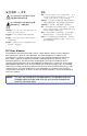
Installation Rear Panel 1 2 3 4 5 6 7 X AU EO VID D 3 6 DV TO AU GE IMA R Projector EC TO OJ PR VC R TE MU PC 1 4 F OF ON 2 5 P PTO LA CON ME FIG 6 IP IR LU C 22 VO Projector ML Extron MLC 226 IP COMPUTER INPUTS 1 2 3 5 7 1 4 6 8 2 COMPUTER OUTPUTS 3 5 9 4 6 10 MediaLink® Controller X AU EO VID D 3 6 DV TO AU GE IMA R EC TO OJ PR S UT TPT OUOU 11 EOEO VID VID 10 TE MU R 2 5 CON ME LU PC P PTO LA FIG K LOC 11 GENVIDEO H 3 Extron
Remote Control Ports e Composite video outputs (Output 7 and Output 8) — Connect composite video displays to these female BNC connectors. NOTE: 3-pole captive screw connectors for serial RS-232 (see figure 4). If the input tied to Output 7 or Output 8 is S-video, the switcher encodes the input to composite video. If the tied input is composite video, the switcher passes it through to the output with no processing.
Front Panel Operations In this chapter, = lit, = unlit, and = blinking. Creating a Tie NOTES: • When creating video and audio ties in the low resolution video group, audio must be redirected (tied to a different, but corresponding, output than the video) because there are only audio outputs 1 through 6. In this case, the audio is tied to an output in the computer video/audio group. • If the video is tied to output 7, the audio is tied to output 1.
3. Press and release the desired input button. The input LED lights to indicate the selection. 5 1. Press the View button. The output LEDs light for outputs that have no ties established. 4. Press and release the desired output button(s). Output LEDs blink to indicate a potential tie. 3 4 8 ENTER NOTES: • If an output button blinks, that output is muted. To toggle mute on and off, press and hold the output button for 2 seconds.
Selecting S-video or Composite Video Low resolution video inputs 11 through 14 are individually configurable as either composite video or S-video. View and change this variable from the front panel as follows: NOTE: The input video format is protected when front panel Lock mode 2 is selected. You can view the selected form of the input in Lock mode 2 but you cannot change it from the front panel (see “Setting the Front Panel Locks (Executive modes)”). 1. Press and hold the Video button until it flashes.
Remote Control Selecting Lock Mode 2 or Toggling Between Mode 2 and Mode 1 NOTE: If the switcher is in Lock mode 0 or mode 1, this procedure selects mode 2. If the switcher in in Lock mode 2, this procedure selects mode 1. Toggle the lock on and off by pressing and holding the Video button and the Audio button simultaneously for approximately 2 seconds. Press and hold the Video and Audio buttons simultaneously to turn on Lock mode 2 or to toggle between mode 1 and mode 2.
14 MPX 866 A • Remote Control 00 – maximum number of inputs for your configuration (00 = untied) 01 – 12 X! = Input number X@ = Output number NOTE: Tie input X! video and audio to output X@. Tie input 1 video and audio to output 3. Tie input 11 video and audio to output 9.
Command/Response Table for SIS Commands Command ASCII Command Response (Host to Unit) (Unit to Host) Additional Description Create ties NOTES: • Video ties cannot be made between the computer video group and the low resolution video group. • Audio ties can only be made to the computer/audio output group (outputs 1 through 6). • Video and audio ties between the low resolution video input group and the low resolution video oputput group are always made with the audio redirected.
16 Command MPX 866 A • Remote Control ASCII Command Response (Host to Unit) (Unit to Host) Tie input X! to output X@, computer only Example (see Notes, above): X!*X@& OutX@•InX!•RGB] 5*4& Out04•In05•RGB] Tie input X! to output X@, video only Example (see Notes, above): X!*X@% OutX@•InX!•Vid] 9*7% Out07•In09•Vid] Tie input X! to output X@, audio only Example: Read computer video output tie X!*X@$ OutX@•InX!•Aud] 12*4$ Out04•In12•Aud] X@& X@% X@! X!] X!] X!] Read video output tie Read
18 Command MPX 866 A • Remote Control ASCII Command Response (Host to Unit) (Unit to Host) Additional Description Audio input gain and attenuation NOTE: The set gain (G) and set attenuation (g) commands are case sensitive. The increment, decrement, and read commands are not case sensitive. Set input audio level to +dB (gain) value Example: X!*X^G 1*2G In01•Aud+02] Set input audio to –dB (attenuation) value Increment level X!*X*g InX!•AudX&] X!+G InX!•AudX&] Increase gain by 1 dB.
20 Command MPX 866 A • Remote Control ASCII Command Response (Host to Unit) (Unit to Host) Additional Description Front panel locks (Executive modes) NOTE: See "Setting the Front Panel Front Panel Locks (Executive Modes)" on page 11 for more detailed descriptions of the lock modes. Lock all front panel functions 1X Exe1] Enable Lock mode 1. Lock advanced front panel functions Unlock all front panel functions 2X Exe2] Enable Lock mode 2. 0X Exe0] Enable Lock mode 0.
Installing and Starting the Control Program Another way to operate the switcher is via the Windows® Matrix Switchers Control Program. This program is contained on the Extron Software Products DVD (included with the switcher). Run this program on a PC connected to to any of the switcher’s three serial ports or the Ethernet port (see item j, item n, and item k on page 5 for connection information. The program must be installed on a Windows-based computer and cannot be run from the DVD.
3. If you selected IP [LAN] in step 2, the IP Connection window appears. 2. Obtain the MAC address (UID #) of the switcher from the label on its rear panel. The MAC address should have this format: 00-05-A6-xx-xx-xx. 3. If the switcher has never been configured and is still set for factory defaults, go to step 4. If not, perform a mode 4 system reset. For detailed information on reset modes, see “Reset Operations” in the MPX 866 A User Guide. NOTE: a.
6. After verifying that the IP address change was successful, enter and issue the “arp –d” command at the DOS prompt. For example: 6. The switcher downloads the HTML start-up page, shown below. The switcher is ready for operation via HTML remote control. arp –d 10.13.197.7 removes 10.13.197.7 from the ARP table or arp –d* removes all static IP addresses from the ARP table.