
Setup Guide Owner's manual
3
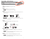
Setup Guide — MP 101 Series
Step 6
Connect the destination device to the MP 101 AAP line output connector. See
Step 4 of this Setup Guide (page 2) for wiring instructions.
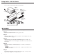
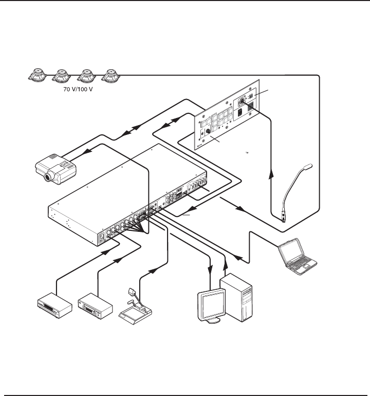
This is a typical setup using the MP 101 AAP preamplifi er.
Extron
MP 101 AAP
MIC to Line
Preamplifier
Podium
Microphone
AUX/MIX Input
Mono Amplified Output
Projector Control
R
100-
2
40V
1.0A M
A
X.
5
0
-6
0
Hz
RS-232
MLC/IR
CONTROL
INPUT 4
AUDIO INPUTS
LINE LEVEL
MONO
AUDIO
AUDIO
Tx
R
x
IR
12V
A
B
C
PREAMP
AUX/MIX
ADJUST
-42dB
TO
+24dB
L
R
L
R
L
R
1
2
3
INPUTS
OUTPUTS
VIDEO
H
V
B
G
R
Y
1
2
3
INPUTS
MONITOR OUT
4
5
6
C
AMPLIFIED OUTPUT
20 WATTS MONO
DIRECT
XFMR
COM
COM
100V
70V
4
8
Extron
MLS 406MA
MediaLink Switcher
Laptop
w/ Audio
RGB
Document
Camera
V
C
R
DVD
Projector
PC
Extron
MLC 226 IP AAP
MediaLink
Controller
PROJECTOR
MLC 226 IP AAP
1
2
3
4
5
6
VOLUME
CONFIG
IR
PC
DVD
VCR
LAPTOP
AUTO
IMAGE
MUTE
ON
OFF
DOC
CAM
UNSWITCHED
100-240V - 5AMAX
MIC
IN
MLP 101 AAP
MUTE
ACTIVE
Typical connection setup
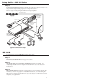
MP 101 D
To install and set up the MP 101 D, follow these steps:
Step 1
Disconnect the MP 101 D from any power source.
Step 2
Set the Mic Gain, Low Cut, Filter, and Phantom power as needed. See
“Adjusting the MP 101 D” in chapter 4 of the MP 101 Series User Guide for
instructions.
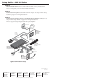
Step 3
Place the MP 101 D through the opening in the wall or furniture and into the
wall box, as shown on page 4. For detailed instructions, see “Mounting the
MP 101 D” in chapter 4 of the MP 101 Series User Guide. For dimensions and a
template, see appendix B.