User’s Manual MMX 32 VGA A Mini Matrix Switcher www.extron.com Extron Electronics, USA 1230 South Lewis Street Anaheim, CA 92805 800.633.9876 714.491.1500 FAX 714.491.1517 Extron Electronics, Europe Beeldschermweg 6C 3821 AH Amersfoort, The Netherlands +800.3987.6673 +31.33.453.4040 FAX +31.33.453.4050 Extron Electronics, Asia 135 Joo Seng Rd. #04-01 PM Industrial Bldg., Singapore 368363 +800.7339.8766 +65.6383.4400 FAX +65.6383.4664 © 2007 Extron Electronics. All rights reserved.
Precautions Safety Instructions • English This symbol is intended to alert the user of important operating and maintenance (servicing) instructions in the literature provided with the equipment. This symbol is intended to alert the user of the presence of uninsulated dangerous voltage within the product's enclosure that may present a risk of electric shock. Caution Read Instructions • Read and understand all safety and operating instructions before using the equipment.
MMX 32 VGA A • Table of Contents i
Table of Contents Chapter 1 • Introduction .......................................................... 1-1 About this Manual ................................................................ 1-2 About the MMX 32 VGA A ................................................ 1-2 Features ...................................................................................... 1-3 Chapter 2 • Installation and Operation ......................... 2-1 Mounting the MMX 32 VGA A ........................................
Table of Contents, cont’d Appendix A • Specifications, Part Numbers, and Accessories .............................................................................. A-1 MMX 32 VGA A Specifications ......................................................................... A-2 Included Parts ......................................................................... A-5 Optional Accessories ...........................................................
Introduction About this Manual Features This manual discusses how to install and operate the Extron MMX 32 VGA A matrix switcher. About the MMX 32 VGA A The Extron MMX 32 VGA A is a compact, three-input, two-output matrix switcher suitable for small installations or portable systems. The switcher routes computer video and both balanced and unbalanced audio signals, and features a bandwidth of 300 MHz to accommodate signals of all resolutions, from VGA to UXGA.
Introduction MMX 32 VGA A 2 Chapter Two Installation and Operation Mounting the MMX 32 VGA A Rear Panel Features and Cabling Front Panel Features and Operation 1-4 MMX 32 VGA A • Introduction
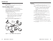
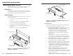
Installation and Operation Use 2 mounting holes on opposite corners. Mounting the MMX 32 VGA A The MMX 32 VGA A can be set on a table, mounted on a rack shelf, or mounted under a desk, podium, or tabletop. 1 OU TP UT 2 1 3 Tabletop use 1 OU TP UT 2 2 3 Four self-adhesive rubber feet are included with the switcher. For tabletop use, attach one foot at each corner of the bottom of the unit, and place the unit in the desired location.
Installation and Operation, cont’d Rack mounting instructions On the standard rack shelf, the switcher mounts in one of four locations to the rear of the rack or in one of four locations to the front of the rack. 4. Drill 3/32" (2 mm) diameter pilot holes, 1/4" (6.3 mm) deep in the mounting surface at the marked screw locations. 5. Insert #8 wood screws into the four pilot holes. Tighten each screw into the mounting surface until just less than 1/4" of the screw protrudes. 1.
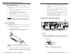
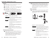
Installation and Operation, cont’d Outputs 7 2 Video output 1 — Connect an output monitor or other VGA device to this female 15-pin HD connector. 3 Audio output 1 — Connect speakers to this 3.5 mm stereo jack. 4 Video output 2 — Connect a projector or other RGBHV video output device to these five BNC connectors. 5 Audio output 2 — Connect speakers to this 5-pole 3.5 mm captive screw connector. Wire the captive screw connector for stereo output as shown in figure 2-6.
Installation and Operation, cont’d Do not tin the stripped power supply leads before installing the captive screw connector. Tinned wires are not as secure in the captive screw connectors and could be pulled out. To verify the polarity before connection, plug in the power supply with no load and check the output with a voltmeter. The two power cord wires must be kept separate while the power supply is plugged in. Remove power before wiring.
Installation and Operation, cont’d MMX 32 VGA A 3 Chapter Three Remote Control RS-232 Control Contact Closure Control 2-10 MMX 32 VGA A • Installation and Operation
Remote Control The switcher’s rear panel Remote connector can be connected to the serial port output of a host device such as a computer or control system, or to a contact closure device such as the Extron MMX 32 AAP panel (part #70-277-01, -11, or -21) or MMX 32 MAAP panel (part #70-277-12 or -22). RS-232 Control The RS-232 Remote connection makes software control of the switcher possible via the Extron Simple Instruction Set (SIS) or the Extron Windows®-based control program.
3-4 X20 = Mute X19 = Controller software version number to second decimal place 0 = no mute 1 = video mute 2 = audio mute 3 = video and audio mute Space ASCII to HEX Conversion Table MMX 32 VGA A • Remote Control OUT X3 IN X2 RGB OUT01 IN3 RGB OUT X3 IN X2 AUD OUT02 IN1 AUD X2 * X3 3*1% X2 * X3 $ 1*2$ % OUT X3 IN X2 ALL OUT02 IN01 ALL X2 * X3 ! 1*2! X3 *1Z/z Audio mute AMT X3 *1 X3 *0Z/z AMT X3 *0 Audio unmute X3 Z/z X9 Read audio mute Global (where X3 is not included, global Audio mute is activa
Remote Control, cont’d 3-6 Firmware can be uploaded two ways: MMX 32 VGA A • Remote Control 2. Using the Esc upload SIS command entered via a communications utility such as HyperTerminal. Extron recommends that you upload firmware using the Universal Switcher Control Program (see Updating the firmware on page 3-12) and reserve this SIS procedure for correcting firmware that has been corrupted and is unable to respond to the Universal Switcher Control Program.
Remote Control, cont’d The firmware upload can take several minutes. If HyperTerminal’s echo function is turned off, you will have no indication that the upload is progressing. If desired, turn on the echo function as follows (figure 3-2): Click File > Properties > Settings > ASCII Setup... and then click the Ok button twice. Figure 3-3 — Select the firmware upgrade file Figure 3-2 — Turn on the echo function 3. Press and release the keyboard’s Esc key and then type upload.
Remote Control, cont’d Windows-based control program The Universal Switcher Control Program is compatible with Windows 3.1/3.11 and later. It provides remote control of the input selection for each output (including audio breakaway) and audio gain and attenuation adjustments. Updates to this program can be downloaded from the Extron Web site (http://www.extron.com). Installing the software The program is contained on a single 3.
Remote Control, cont’d Updating the firmware Firmware updates periodically become available on the Extron Web site. To load a firmware update: Using the help system For information about program features, you can access the help program in any of the following ways: 1. Download the update file from the Extron Web site (www.extron.com). • From the Extron Electronics program group, double-click the Signal Enhancement Products Help icon. 2. Run the Universal Switcher Control Program. • 3.
Remote Control, cont’d Connecting an MMX 32 AAP or MMX 32 MAAP control panel Each Extron MMX 32 AAP and MMX 32 MAAP contact closure remote control panel can control one output on the switcher. To connect a panel to the switcher, wire the captive screw connectors on the rear of the panel as follows. 3 4 Tally Power connector 4 5 VDC pole — Connect this pole of the captive screw connector to the 5 VDC pole of the Tally Pwr connector on the MMX 32 VGA A.
Remote Control, cont’d MMX 32 VGA A A Appendix A Specifications, Part Numbers, and Accessories Specifications Included Parts Optional Accessories 3-16 MMX 32 VGA A • Remote Control
Specifications, Parts, and Accessories Specifications Video Routing .......................................... 3 x 2 matrix Gain ............................................... Unity Bandwidth .................................... 300 MHz (-3 dB), fully loaded 0 – 10 MHz ................. no more than +0.1 dB to -0.1 dB 0 – 130 MHz ............... no more than +2 dB to -0.1 dB Crosstalk ....................................... -55 dB @ 10 MHz, -45 dB @ 30 MHz, -37 dB @ 100 MHz Switching speed ................
Specifications, Parts, and Accessories, cont’d Control/remote — switcher Serial control port ........................ Baud rate and protocol ............... Serial control pin configurations Contact closure ............................