User Guide AV SWITCHERS MLS 608 D SERIES AV Switchers with ProDSP™ (with the MTP/HDMI U R receiver) MLS 608 D SA MTP/HDMI U R 68-1893-01 Rev.
Precautions Safety Instructions • English Warning This symbol is intended to alert the user of important operating and maintenance (servicing) instructions in the literature provided with the equipment. Power sources • This equipment should be operated only from the power source indicated on the product. This equipment is intended to be used with a main power system with a grounded (neutral) conductor. The third (grounding) pin is a safety feature, do not attempt to bypass or disable it.
FCC Class A Notice This equipment has been tested and found to comply with the limits for a Class A digital device, pursuant to part 15 of the FCC Rules. Operation is subject to the following two conditions: 1. This device may not cause harmful interference. 2. This device must accept any interference received, including interference that may cause undesired operation.
Conventions Used in this Guide In this user guide, the following are used: NOTE: TIP: A note draws attention to important information. A tip provides a suggestion to make working with the application easier. CAUTION: WARNING: A caution indicates a potential hazard to equipment or data. A warning warns of things or actions that might cause injury, death, or other severe consequences.
Introduction............................................................ 1 DSP Configurator™.............................................. 44 MLS 608 D Series Description............................... 1 Features............................................................... 1 Controlling the MLS 608 D Series Switcher.......... 3 MLS 608 D SA Application Diagram .......................................................................... 4 Installing the Software.......................................
MLS 608 D Series • Contents vi
Introduction This manual contains information about the Extron MLS 608 D Series of AV switchers with instructions for experienced installers on how to install, configure, and operate it. In this manual the terms “MLS 608 D Series switcher,” “AV switcher,” and “switcher” are used interchangeably and refer to any of the MLS 608 D Series models. MLS 608 D Series Description The MLS 608 D AV switchers are available in three models: zz MLS 608 D — a non-amplified model with variable preamp outputs.
zz EDID Minder® — Automatically manages EDID – Extended Display Identification Data – communication between the display and connected VGA and HDMI input sources. EDID Minder ensures that all sources power up correctly and reliably output content, whether or not they are actively connected to the display device through the switcher outputs. zz HDMI audio de-embedding — Strips two-channel PCM audio off HDMI inputs, allowing for DSP processing and signal routing.
zz Essential audio DSP tools — ProDSP provides an extensive array of easy-to-use, digital audio processing tools for audio system setup and fine-tuning, including audio gain, dynamics, compression, filtering, delay, microphone ducking, loudness, and feedback suppression.
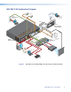
MLS 608 D SA Application Diagram CH Extron MTP T 15HD A D DIO IN TCP/IP Network Microphones 003 CH Help Desk Monitoring and Control 003 Ethernet Transmitter AU R IN TE MPU CO Projector Control Tx L NT R & VC D RO CO DVD DV VCR TUN ER NU P STO ME ER SE ENT WD LE Switcher Control TO AU GE IMA Y LA SP DI R VC 1 4 2 5 3 6 EW Y PLA NEX V/R PRE PC MLC 226 IP DV + C DO M CA F OF OP PT LA ON D PAU T/F TIT X AU EO VID DV IG NF CO ME LU IR VO
Installation This section contains installation information for an MLS 608 D Series device and covers the following subjects: zz UL/Safety Requirements zz Mounting the MLS 608 D Series Switcher UL/Safety Requirements The Underwriters Laboratories (UL) requirements listed below pertain to the safe installation and operation of this AV Switcher. 1. Read these instructions. 2. Keep these instructions. 3. Heed all warnings. 4. Follow all instructions. 5. Do not use this apparatus near water. 6.
Mounting the MLS 608 D Series Switchers If the device is to be rack mounted, it may be easier to do so before cabling it, depending on the ease of access to the rear panel after mounting. Four rubber feet are included with the unit. Install the feet only if the unit is to be mounted on a tabletop (see “Tabletop placement” below). Tabletop Placement For tabletop placement, install the self-adhesive rubber feet/pads (provided) onto the four corners of the bottom of the device.
Rear Panel Connections This section describes the rear panel features and how to connect the cables to the MLS 608 D and to the MTP/HDMI U R as applicable. MLS 608 D Series Rear Panel Features This illustration shows all possible features of the MLS 608 D Series.
Power, Analog, and Digital Connections a Power input — Connect the standard IEC power cord from a 100 to 240 VAC, 50 Hz or 60 Hz power source into this connector. The front panel control and input selection buttons light in sequence during power-up. b Inputs 1-3 — These three universal analog input ports (15-pin HD [VGA] connectors) can be configured to accept RGB (RGBHV, RGBs), component (bi- or tri-level), S-video, or composite video signals. The default setting is for RGB.
c Buffered output — This buffered analog output is tied only to input 1 and is a direct pass-through from any video signal, such as composite, S-video, RGBs, and YUV, that is present on input 1. CONFIGURABLE ANALOG INPUTS 1 BUFFERED OUTPUT Connect a local output to this 15-pin HD (VGA) connector for a buffered analog output from input 1. The set signal type is output on the VGA connector, however, for composite, S-video, RGBs, and YUV signals, break out cables are needed when connecting a display.
MLS 608 D Analog Signal Transmission Distance Table for Inputs and Outputs, in Feet and (Meters) NOTE: • The maximum transmission distances are determined by the frequency and resolution of the video signal being routed. The table below specifies the recommended maximum distances when using Extron Enhanced Skew Free AV UTP cable or UTP CAT 5, 5e, or CAT 6 cable, terminated with RJ-45 connectors. • The minimum TP cable length should be 25 feet from the MTP Tx to input 4.
f Analog MTP output (audio and video) — This output transmits signals from an active analog input over CAT 5 cable to the MTP/HDMI U R receiver. It is also capable of transmitting line level mono audio over the same cable as audio output 3. The output also supports pre-peaking adjustment for optimizing video signals for long cable runs. Skew adjustment is available on this ouput, compensating for up to 64 nanoseconds of skew. Adjustments are made using DSP Configurator software or SIS commands.
4. Loosely place the included tie wrap around the HDMI connector and LockIt lacing bracket. 5. While holding the connector securely against the lacing bracket, tighten the tie wrap, then remove any excess length. The LockIt bracket can be mounted in different orientations, as shown below.
NOTES: • Transmission distance varies greatly depending on the signal resolution, and the type of cable, graphics card and display used in the system. • Shielded twisted pair cable provides added protection from outside interference and increases overall signal transmission distance. Extron recommends using shielded twisted pair for optimal performance. When using STP cable, terminate the cable as follows: 1. For each cable, peel back the cable shielding from the end of the cable 7/8 inch [2.
Audio and RS-232 Connections NOTES: When wiring the connectors for the ports listed below: • DO NOT tin the wires. • Bare the wires to a maximum length of 3/16 inch (5 mm) only. i Audio inputs 1-3 and 5-8 — These 5-pole captive screw connectors support analog, balanced or unbalanced, stereo audio as three line level inputs (1-3) and four line level analog stereo inputs (5-8). Audio from the HDMI inputs 5-8 can be de-embeded from the HDMI source.
£ 12a L R § Power amplifier output (MLS 608 D SA) — This model has a 2x20 watt stereo power amplifier Connect a suitable audio device for 2-channel stereo, 20 watts per channel, 4 or 8 ohm audio output. Wire the connector as shown at right To 4/8 Ohm Speaker Load Power amplifier output (MLS 608 D MA) — This model has a 40 watt, 70 volt, mono power amplifier. Connect a suitable audio device for mono audio, 40 watts, 70 volt audio output. Wire the connector as shown at right.
RS-232 Insert — This port is used to connect an optional control device (such as an MLC 226 IP or IP Link controller) to this port for bi-directional RS-232 communication to a display device. This insert port is tied to the MLS 608 D digital and RS 232 output ports, h.
MTP/HDMI U R Connections The full MLS 608 D system comes with an MTP/HDMI U R receiver. To work with any of the MLS 608 D units, connect the receiver as shown below. Power input MTP input RS-232 port (analog side).
RS-232 control (digital side) — Connect a serial communications port on a display device to the 3.5 mm, 3-pole captive screw connector (labeled RS-232 pass-thru) for pass-through RS-232 bidirectional communication. Wire the connector as shown at right. NOTE: RS-232 Device Pins Rx Tx Tx Rx MTP/HDMI RS-232 Pass-thru port Ground RS-232 control port on the analog side is not used in the MLS 608 D system. Power connection — Connect the 2-pole 3.5 millimeter captive screw connector from the 12 VDC, 1.
Power Save Mode Power Save mode is a feature on the MLS 608 D that will help conserve energy and reduce costs by placing the unit into a standby state. The switcher does not have an auto-power down feature (like the one used on the XPA 1002, for example), and can only be placed into the standby state via an SIS command. Sending the SIS command E1PSAV] turns on the power save mode.
Operation This section of the manual discusses the operation of an MLS 608 D device, and is divided into four sections: zz Front Panel Features and Operation zz Using EDIDs zz Optimizing Audio — An Overview zz Optimizing Video — An Overview zz Firmware Upgrades Front Panel Features and Operation All MLS 608D models have the same front panel configuration.
Mode 5 — Reset the MLS 608 D to factory default (except firmware). To reset the device to factory defaults (with the exception of the firmware), press and hold in the reset button for approximately 9 seconds, until the LED blinks three times (once at 3 seconds, once at 6 seconds, and once again at 9 seconds). Release and within 1 second press the reset button once (<1 second). NOTES: Nothing will happen if the momentary press is not made within 1 second.
Use this volume adjustment knob to set or adjust the program output volume (attenuation, from -100 dB to 0 dB) as desired. The LEDs indicate the overall percentage level for Group Master 1; the volume level being all off (0%) at -100 dB through to all on (100%) at -4 to 0 dB. Any level changes made do not affect the mic audio. Rotate the knob clockwise to increase volume, counter-clockwise to decrease volume. The corresponding LEDS light as the knob is rotated. See the table at right for LED/dB values.
EDID Resolution/Refresh Rate Combination with SIS Variables (where X2! = 1 through 64)* Digital Signal Resolution Refresh Rate (Hz) Automatic Mode (digital only) Analog Signal SIS value for X2! Resolution Refresh Rate (Hz) SIS value for X2! 0 800x600 60 29 800x600 60 1 1024x768 (default) 60 30 1024x768 60 2 1280x768 60 31 1280x768 60 3 1280x800 60 32 1280x800 60 4 1280x1024 60 33 1280x1024 60 5 1360x768 60 34 1360x768 60 6 1366x768 60 35 1366x768 60 7 1440x9
Automatic EDID Mode (digital output only) In this mode, if no displays are connected, the default EDID (720p @ 60 Hz, with 2-channel PCM audio support) is present as the native resolution at each HDMI input. When a display is connected to the digital output, the EDID of that display is automatically read and stored, and the default EDID is overwritten for each HDMI input. The reading and storage of the new data is triggered by the Hot Plug Detect signal (HPD) the moment the display is detected.
User Loaded EDID – Digital The EDID of a display connected to the HDMI output of the MTP/HDMI U R receiver (see on page 17) can be read and stored to the digital user loaded spaces 3 or 4 (SIS values 51 and 52, see figure 14). This can be recalled later as the user assigned EDID. To save the digital output EDID information to the User 3 or User 4 location in the EDID table: 1. Connect the display to the digital output on the MTP/HDMI U R receiver. 2.
3. From the Configuration to export drop-down list, select the desired EDID configuration to export. This can include EDID information that is stored at one of the available user-defined locations. 4. Click OK. The Save As dialog box opens. 5. Navigate to the location where the configuration is to be saved. 6. In the File name field, enter a name for the file or leave the original file name. 7. Click Save. EDID Configuration files are saved with a BIN extension.
Optimizing Audio — An Overview Audio optimization is performed using the DSP Configurator application. The application provides audio level and DSP processing controls that include audio gain, dynamics, filtering, delay, ducking, and feedback suppression, essential for setting up and configuring audio systems. When configuring an MLS 608 D Series device, DSP Configurator has four workspaces from which you can configure and view processing blocks, mix-points, and audio and video ties in the system.
DSP Signal Chain The DSP signal chain is in a fixed order and each processor block inserts only one category of processor. However, the signal chain is also flexible in that a variety of processor types can be inserted per processor category. Processor blocks are placed in the signal chain pre- and post-switcher to perform specific tasks. There are level control blocks, signal processor blocks, and mix-point blocks (with level control).
b Filter (FILT) — Up to three frequency filters can be inserted in any combination of High Pass, Low Pass, Bass & Treble filters, or Parametric Equalizer. c Dynamics 1 (DYN) — Dynamics processors vary the dynamic level, (the range of loudest to softest signals). Choices include AGC, compressor, limiter, or noise gate. d Dynamics 2 (DYN) — A second dynamics processor can be inserted from a choice of AGC, compressor, limiter, or noise gate. e Delay (DLY) — Delay can be set either by time or distance.
f Filter (FILT) — Up to nine frequency filters can be inserted in any combination of high pass, low pass, tone (bass and treble shelving), or parametric. g Dynamics (DYN) — A single dynamics processor can be inserted from a choice of AGC, compressor, limiter, or noise gate. h Volume (VOL) — Left and right faders adjust stereo output volume from -100 to 0 dB and includes a mute control. A polarity switch (+/-) is provided and a meter displaying output audio level in dBFS (decibels relative to full scale).
Building Blocks — An Overview Extron building blocks are a quick configuration tool that can significantly reduce device configuration time. A building block is a collection of processor and gain settings for a particular portion of the signal chain. This allows configuration of an entire mic input, line input, or line output channel with just two clicks. A comprehensive set of pre-configured building blocks is placed on your computer system as you install DSP Configurator.
Line input building blocks Extron building blocks for line level devices set the gain level for the specific device and its operating line level. Bass and treble shelving filters are inserted into the filter block, with gain level set to 0 dB. This allows for tone adjustment, if necessary, either via the DSP Configurator software or by programming the gain parameters into a control system and allowing the user to make adjustments.
The purpose of the speaker building blocks is to normalize the inherently non-linear response of a ceiling speaker array, as opposed to flattening the on-axis response of a single speaker. Depending upon the source, additional sweetening of the signal may be desired. For microphones, a high pass filter should be employed to eliminate popping and in certain cases, tone shaping of the speech range may be desired. For music sources, a bass boost is often employed to sweeten the sound at lower levels.
Modifying and adding a building block Building blocks can be modified and saved to give you a customized set of tools that are unique to your needs. Any mix-points that are associated with a signal path are not saved and recalled with the associated signal chain building block. You can create a building block from an existing configuration to be used in the future (such as for another input or in another configuration file). To create a building block: 1.
Group Masters — An Overview There are 32 group masters that can each be configured to control up to 16 group members. For the MLS 608 D Series, there are five pre-configured group masters. zz Program Volume — Groups gain controls at the post-switcher gain point. Default membership includes channels 1, 3, and 4 (MA and SA models). The default gain value is -10 dB. zz Mic Volume — A gain control at the pre-mixer gain points in the mic/line signal chain. Default membership is channels 1 and 2.
Configuring Groups For an MLS 608 D Series device, five group masters are pre-configured and relate to program volume, mic volume, output bass, output treble, and volume mute. These groups cannot be deleted; however, group membership can be modified. To modify a pre-configured group: 1. From the Tools menu, select Configure Groups. The Configure Groups dialog box opens. - or From the View menu, select Group Controls and click Add a Group in the Group Controls dialog box.
To delete a group: 1. In the Configure Groups dialog box, select a group from the Select Group dropdown list and click Delete Current Group. The Confirm Deletion dialog box opens. Figure 17. Configure Groups Dialog Box 2. Click Yes to delete the group. Viewing Group Controls From the View menu, select Group Controls to open the Group Controls dialog box. You can resize this window as needed. The Group Controls dialog box contains two items in the menu bar: zz Add a Group zz Tools Figure 18.
Tools The Tools menu in the Group Controls dialog box contains four options: zz Clear All Groups — Clicking this option clears all group members and group master parameters. zz Increment/Decrement Simulator — Clicking this option allows you to test the increment and decrement values (see below for more information). zz Refresh All Group Data — Clicking this option refreshes the group control data.
To adjust the upper limit, press and hold the key. zz Hold and press or to adjust the upper limit in 0.1 dB increments. zz Hold and press or to adjust the upper limit in 10 dB increments. zz Hold and press to adjust the limit to the upper default. zz Hold and press to move the limit to the fader position. To adjust the lower limit, press and hold the key.
Optimizing Video — An Overview After the input and output connections have been completed, both the MLS 608 D and the MTP/HDMI U R need to be configured to optimize the video. Setting the Peaking and Level on the MTP/HDMI U R Image sharpness is adjusted with the Peaking control. This applies only to the analog side of the device. Increased peaking compensates for mid- and high-frequency detail loss. Minimum setting (full counterclockwise) is zero peaking.
Setting the Skew on the MLS 608 D To adjust output skew between the MLS 608 D and the receiver: 1. Connect an oscilloscope (preferred) or a monitor (acceptable) to the RGB output on the MTP/HDMI U R. 2. Apply a crosshatch test pattern to the inputs 1, 2, or 3 on the MLS 608 D. 3. Use the test equipment or examine the video image with a critical eye to determine which video signal (red, green, or blue) is most shifted to the left. 4.
Firmware Upgrades Within the DSP Configurator software, the Firmware Loader option (click Tools > Firmware Loader) opens the Extron Firmware Loader application, allowing the user to to load new firmware to their device, through either serial or USB connection. In order for the Firmware Loader option to work, you must have the Firmware Loader application installed. To download Firmware Loader from the Extron website: 1. Open an Internet browser window and in the Address field, enter www.extron.com. 2.
4. Click Open. This closes the Choose Firmware File dialog box and returns you to the Firmware Loader main screen. 5. Click Begin. This uploads the new firmware onto your connected device. The Progress bar for the selected device shows the progress of the upload. After the upload is complete, this field is blue and shows 100%. Figure 20. Firmware Loader — Loading Complete 6. Exit Firmware Loader.
DSP Configurator ™ As the MLS 608 D Series of switchers are ProDSP™-capable products, the Extron Digital SIgnal Processor (DSP) Configurator application can be used as a configuration tool via RS-232 or front panel USB connection. The DSP Configurator provides access to audio level and DSP processing controls that are essential for setting up and configuring audio systems.
2. If the disc does not start automatically, run LAUNCH.EXE from the disc. 3. Follow the instructions that appear on the screen. By default, the installation creates a C:\Program Files\Extron\DSP_ Configurator directory and places a shortcut icon in it. NOTE: During initial installation, the user is asked if they wish to install the USB drivers or not.
Figure 32. The Default Audio and Video I/O Workspace in Emulate Mode For the MLS 608 D, the DSP Configurator has four workspaces: zz Audio and Video I/O workspace zz Audio I/O workspace zz Video I/O workspace zz Console View workspace Each workspace provides a map of all input and output signal paths inside the main application window.
Using the DSP Configurator Software The typical normal method of using DSP Configurator is to: 1. Create a configuration and a set of presets in Emulate mode. 2. Save the file. 3. Push (upload) the file to the device. Emulate mode allows you to work within the program offline, creating or editing configurations. In Emulate mode the current configuration is titled Current Emulation, while in Live mode the current configuration is titled Current State.
Workspace Menus NOTE: For detailed DSP Configurator instructions when the program is open, press or click on Help > Contents. File menu Click on this to open a drop-down menu displaying seven selectable options: New, Open, Save, Save As, Backup, Recent Files, and Exit. zz New — Select this to create a new configuration. NOTE: When in Live mode, the New option is disabled. zz Open — Select this to open an existing configuration (an .EDC file).
View menu Click on this to open a drop-down box displaying six selectable options, including four workspaces: Audio & Video I/O, Audio I/O, Video I/O, and Console View, and Re-enable All Dialogs and Group Controls menus.
zz Audio I/O — The Audio I/O workspace is used for viewing and configuring audio ties in breakaway mode. This workspace contains all audio, gain, trim, volume, and audio DSP processor settings. is the shortcut key. Figure 35. The Audio I/O Workspace in Live Mode zz Video I/O — The Video I/O workspace is used for viewing and configuring video ties in breakaway mode. This workspace contains the low-resolution video input, RGB delay, and video mute settings. is the shortcut key.
zz Console View — This is used to provide access to all gain points plus a meter bridge in a single view. This is useful for fine tuning gain structure during system testing and commissioning. is the shortcut key. Figure 37. The Console View in Emulate Mode Other View menus zz Re-enable All Dialogs — Selecting this option re-enables all dialogs that were disabled and currently no longer appear (based on user selection), such as the notification dialog when a preset was saved.
Tools menu Click on this menu to open a drop-down list: Presets, Protected Configuration, Configure EDID, Connect to Device, Issue RESET Command, Save Changes to Device, Firmware Loader, Organize Building Blocks, Configure Groups, Device Settings, and Options. NOTE: zz Connect to Device menu changes to Disconnect from Device when a device is connected. Presets — Selecting this option brings up four submenus: Mark All Ties, Mark All Items, Save Presets, and Clear Marked Items.
zz Configure EDID — Selecting this option opens a window that allows adjustments to be made to the EDID settings for analog inputs 1 through 3 and digital inputs 5 through 8. The EDID information provided at the analog or digital output can be stored to a selectable location. Any changes are made directly on the inputs. The EDID configuration option is available only in Live mode.
zz Issue RESET Command — Selecting this option allows the user to reset all the device settings, except the COM settings, to the factory default values. This option is available only when in Live mode. zz Save Changes to Device — Selecting this option allows any configuration changes made to be saved directly to the device. This option is only available in Live mode. zz Firmware Loader — Selecting this option opens the Extron Firmware Loader application.
zz Organizing Building Blocks — Selecting this option allows the organization of listed building blocks. A building block is a collection of processor and gain settings for a particular portion of the signal chain. This allows configuration of an entire mic input, line input, or line output channel with little effort. Building blocks files can be imported and exported for use on other computers and devices.
zz Device Settings — Select this option to change the RS-232 port baud rate and set the current Executive mode (front panel lockout). This is available only in Live mode. Options — Select this option to open a dialog box to set default and user preferences. Selections are made from a drop-down list activated by a topic selection. For complete details of changing options, see the DSP Configurator Help file.
MTP Video Settings RGB Delay During switching, the MTP video output can be set to switch the input sync source first, followed by the RGB portion of the signal. This brief delay allows the display to adjust to the new sync signal before sending the picture, providing a glitch-free switch. RGB delay can be set from 0 to 5 seconds in 0.5-second increments. NOTE: The RGB delay only takes effect if the video input format is set to RGB.
Input MTP settings Each R, G, and B channel can skew up to 62 nanoseconds total (2 nanoseconds per step, 31 steps total). To set the input skew: 1. Connect an oscilloscope (preferred) or a monitor (acceptable) to the VGA output of the MTP/HDMI U R receiver. 2. Apply a crosshatch pattern to the input to be optimized. 3. Use the test equipment or examine the displayed video image with a critical eye to determine which video signal (red, green, or blue) is most shifted to the left. 4.
Output MTP settings To set the output skew: 1. Connect an oscilloscope (preferred) or a monitor (acceptable) to the VGA output of the MTP/HDMI U R receiver. 2. Apply a crosshatch pattern to the input to be optimized. 3. Use the test equipment or examine the displayed video image with a critical eye to determine which video signal (red, green, or blue) is most shifted to the left. 4. From the View menu in DSP Configurator, select Video I/O to open the Video I/O workspace.
The HDCP Status section of the workspace is enabled while in Live mode and displays the following details: zz If an HDCP-compliant source is detected on the inputs, the indicator for the associated inputs are shaded light green. zz If the active source is HDCP-compliant and the connected display is non-HDCP compliant, the output indicator is shaded dark green. If the connected display, is not HDCP compliant, the MLS 608 D Series device mutes the output.
SIS Programming and Control The MLS 608 D units can be remotely controlled via a host computer or other device (such as an optional MLC 226 control system) attached to the rear panel RS-232 connector or the front panel USB configuration port. The device can be configured and controlled by the Extron Simple Instruction Set (SIS™) of commands or by using the Extron DSP Configurator software program. This section describes SIS communication and control.
Error Responses When the switcher receives a valid command, it executes the command and sends a response to the host device. If the unit is unable to execute the command because the command contains invalid parameters, it returns an error response to the host.
Command and Responses Using the Command/Response Tables The following pages detail commands that can be sent to the MLS 608 D via the Extron Data Viewer (available free at www.extron.com) and connected via the front panel mini USB config port or via the rear panel RS-232 port using HyperTerminal.
X* = Master volume value, 0 to -100 dB, in 0.1 dB steps. For example 0 = 0 dB, -1 = -0.1 dB, -10 = -1.0 dB, -100 = -10 dB, -1000 = -100 dB. See table below. Master volume values, X* = (SIS value) dB value SIS value % Output volume dB value SIS value % Output volume dB value SIS value % Output volume dB value SIS value % Output volume 0 0 100 -21.0 -210 79.0 -51.0 -510 49.0 -81.0 -810 19.0 -0.1 -1 99.9 -22.0 -220 78.0 -52.0 -520 48.0 -82.0 -820 18.0 -0.2 -2 99.8 -23.
X1# = Mic number (mute inputs): 40000 = Mic 1, 40001 = Mic 2 X1$ = Audio inputs 1-10: 1-8 = program audio inputs, 9 = Mic 1 input, 10 = Mic 2 input. X1% = Audio output number: 1-4 X1^ = Input signal peaking adjustment range: 0-255 X1& = Skew adjustment value: 0-31, in 2 ns increments (for example 31 = 62 ns) X1* = Video plane: 0 = red, 1 = green, 2 = blue X1( = Input signal level adjustment range: 0-255 (default = 60). X2) = Output bass/treble master value (240 to -240, default = 0), multiplied dB by 10.
EDID Resolution/Refresh Rate Combination with SIS Variables (where X2! = 1 through 64)* Digital Signal Resolution Refresh Rate (Hz) Automatic Mode (digital only) Analog Signal SIS value for X2! Resolution Refresh Rate (Hz) SIS value for X2! 0 800x600 60 29 800x600 60 1 1024x768 (default) 60 30 1024x768 60 2 1280x768 60 31 1280x768 60 3 1280x800 60 32 1280x800 60 4 1280x1024 60 33 1280x1024 60 5 1360x768 60 34 1360x768 60 6 1366x768 60 35 1366x768 60 7 1440x9
X4# = Executive mode (front panel lock): 0 = off (all unlocked, default), 1 = lockout all (input buttons and encoders), 2 = lockout input buttons only X4$ = Baud rate: 300, 600, 1200, 1800, 2400, 3600, 4800, 7200, 9600, 28800, 38400 (default), 57600, 115200 X4% = Parity, Odd, Even, None (default), Mark, Space, (only use first letter, for example N = None) X4^ = Data bits: 7, 8 (default = 8) X4& = Stop bits: 1, 2 (default = 1) X4* = Verbose mode: 0 = no verbose mode and non-tagged responses for queries, 1 =
X5$ = Mic value: 0 to -100 dB, in 0.1 dB steps. For example 2048 = 0 dB, 2047 = -0.1 dB, 2038 = -1 dB, 1948 = -10 dB, 1048 = -100 dB. See table below. Mic Pre-mixer Gain Values, X5$ = (SIS value) dB value SIS value % volume dB value SIS value % volume dB value SIS value % volume dB value SIS value % volume 0 2048 100 -21.0 1838 79.0 -51.0 1538 49.0 -81.0 1238 19.0 -0.1 2047 99.9 -22.0 1828 78.0 -52.0 1528 48.0 -82.0 1228 18.0 -0.2 2046 99.8 -23.0 1818 77.0 -53.
Command Response Table for SIS Commands Command ASCII Command (host to switcher) Response (switcher to host) Additional Description Input Selection Select video and audio input X!! ChnX!] Select a video and audio input source X! View current input ! X!] View currently selected input source X!. Select a video input X!& VidX!] Select a video only input source X!. View current video input & X!] View currently selected video input source X!.
Command ASCII Command (host to switcher) Response (switcher to host) Additional Description Set Group Master Value Set value (dB) NOTE: EDX^*X*GRPM} GrpmDX^*X*] Set the value X* for group number X^. Reserved groups are: 1 = program volume, 2 = mic volume, 3 = output bass, 4 = output treble, 5 = output volume mute. Audio mute or unmute EDX^*X%GRPM} GrpmDX^*X%] Mute or unmute X% for group number X^. Increment value EDX^*X&+GRPM} GrpmDX^*X&] Increase the value by X& for group number X^.
Command ASCII Command Response (host to switcher) (switcher to host) Additional Description Output Bass Adjustment (Group Master 3) ED3*X2)GRPM} GrpmD03*X2)] Set the gain value X2) for group master 3. Example: ED3*240GRPM} GrpmD03*+00240] Sets the gain value to +24 dB. Example: ED3*0GRPM} GrpmD03*+00000] Sets the gain value to 0 dB. Example: ED3*-100GRPM} GrpmD03*-00100] Sets the gain value to -10 dB. Increment gain ED3*X&+GRPM} GrpmD03*X2)] Increase the gain value X2) by X&.
Command ASCII Command (host to switcher) Response (switcher to host) Additional Description RGB Delay Time NOTE: RGB delay affects only inputs 1-3 and if they are configured to RGB format. Set RGB delay EX$D} DlyX$] Set RGB delay to (X$ x 0.5) seconds. View setting ED} X$] View RGB delay setting. MTP Output Pre-peaking Set output pre-peak on E1Opek} Opek1] Turn output pre-peak on. Set output pre-peak off E0Opek} Opek0] Turn output pre-peak off (default).
Command ASCII Command (host to switcher) Response (switcher to host) Additional Description Input Skew Adjustment Set input skew values EX1&*X1&*X1&ISEQ} IseqX1&*X1&*X1&] Set input skew values X1& for R, G, and B signals (IseqR*G*B). Increment one input skew value EX1*+ISEQ} IseqX1&*X1&*X1&] Increase the skew value of X1* by 1. Decrement one input skew value EX1*-ISEQ} IseqX1&*X1&*X1&] Decrease the skew value of X1* by 1. View current values EISEQ} X1&*X1&*X1&] View skew values.
Command ASCII Command (host to switcher) Response (switcher to host) Additional Description EDID Management Assign EDID data to inputs (analog and digital inputs) EAX2@*X2!EDID} EdidAX2@*X2!] Assign EDID data X2! to inputs VGA or HDMI X2@ View EDID data assigned EAX2@EDID} X2!] View EDID data assignment. Save an output EDID to (analog) user loaded space ESX2#*X2$EDID} EdidSX2#*X2$] Save display EDID to analog user space.
Command ASCII Command (host to switcher) Response (switcher to host) Additional Description Power Save Mode Turn power save off E0PSAV} PsavX3$] Turn power save on E1PSAV} PsavX3$] View power save EPSAV} X3$] View power save status. Front panel security lockout (Executive Mode) Enable Executive mode 1 1X Exe1] Lock out front panel buttons and knobs. Enable Executive mode 2 2X Exe2] Lock out front panel buttons only. Disable Executive mode 0X Exe0] Unlock all front panel controls.
Command ASCII Command (host to switcher) Response (switcher to host) Additional Description Reset (Zap)/Erase Commands Reset all video and audio settings to factory default EZXXX} Zpx] Resets all video and audio settings. Reset all settings to factory default EZQQQ} Zpq] Resets all video and audio settings, protected, configuration, verbose mode, and control port settings. NOTE: This command is the same as reset mode 5. See the Mode 5 details in the "Operations" section.
User Interface Navigation This section describes the use of the PC mouse and keyboard, including the associated hot keys used when configuring the MLS 608 D device with DSP Configurator. Topics that are covered include: zz Mouse and Keyboard Navigation zz Keyboard Shortcuts Mouse and Keyboard Navigation Mouse navigation in the DSP Configurator application is mostly consistent with standard Microsoft® Windows® behavior.
Copying a Block of Elements 1. Select the elements to be copied 2. Use one of the following methods to copy the elements: zz Right-click the selection and select Copy from the drop-down menu. zz From the Edit menu, select Copy. zz Press on the keyboard. Cutting a Block of Elements When an element is cut, the element is not removed until it has been pasted. 1. Select the elements to be cut (see the "Selecting Multiple Blocks" and "Selecting Multiple Areas" subsections above). 2.
Pasting to Multiple Locations A selected block of elements can be cut or copied, then pasted to multiple locations. To paste a block of elements to multiple locations: 1. Click the upper left-most element that matches the upper left-most element of the area that you cut or copied. 2. Press and hold the key while repeating step 1 for every area to which you want to paste. Make sure that the area to which you are pasting will not overlap. 3. Release the key. 4.
Keyboard Shortcuts The following is a list of keyboard shortcuts (or strokes) used in navigating and using the DSP Configurator. Not included in this list is the use of the menus via keyboard strokes, for example using , the Edit > Paste menu instead of . Details of those strokes, if needed, can be found in the DSP Configurator Help file. Action Key Press Open DSP Configurator Help file, or, when within a dialog box, open context-specific help.
Action Key Press Select, cut or copy, and paste multiple elements (sequence of keystrokes) 1. Navigate to the block where elements are to be selected. NOTE: Press to go directly to the start of an element block. 2. Select multiple elements. NOTE: and repeatedly, as needed. Press and hold . Use the and or to select elements. Release when all desired cells are selected. Selected elements show a green border. 3.
Button Labels This section describes the procedure for replacing button labels. In this section, a strip of blank button labels is provided. If desired, photocopy them or cut them out of the manual, write button information in each button area, and put them in the applicable input or output buttons. You can also create labels using the free Extron Button-Label Generator software, which is available at www.extron.com.
5. Save the translucent, white diffuser, but remove the text/label insert from the transparent button cap lens. 6. Insert the replacement button label into the button cap. Check for correct label orientation. 7. Align the white diffuser plate with the cap (lens). The bumps on the diffuser plate should be aligned (top and bottom) with the notches on the clear button cap. Firmly snap it into place. 8. Align the tabs on the plunger with the notches on the diffuser plate.
Reference Material This section provides information about: zz Specifications zz Part Numbers and Accessories Specifications Video — MLS analog inputs Gain ����������������������������������������������� Differential phase error ������������������� Differential gain error ��������������������� Crosstalk ���������������������������������������� Switching speed ����������������������������� Skew compensation ����������������������� Signal transmission distance, analog Unity 1° at 3.58 MHz and 4.
Nominal level ��������������������������������� 1 Vp-p for Y of component video and S-video, and for composite video 0.7 Vp-p for RGB and for R-Y and B-Y of component video 0.3 Vp-p for C of S-video Minimum/maximum levels Inputs 1-3 RGB ����������������������������������� Analog: 0.3 V to 1.5 Vp-p with no offset S-video, composite video ���� Analog: 0.4 V to 2.0 Vp-p with no offset Input 4 RGB ����������������������������������� Analog: 0.3 V to 1.
Audio — MLS Gain Input 4 ������������������������������������ Unbalanced output: 0 dB; balanced output: 6 dB All other inputs ������������������������ Unbalanced output: -6 dB; balanced output: 0 dB Frequency response Power amp (MA model) ����������� 80 Hz to 20 kHz, -3 dB to +1 dB @ 1 watt output (11 Vrms) Power amp (SA model) ������������ 20 Hz to 20 kHz, -3 dB to +1 dB @ 1 watt output, 8 ohm load Input 4 Lineout ������������������������������ 20 Hz to 20 kHz, ±0.
Input gain adjustment Mic/line input �������������������������� -18 dB to +80 dB, adjustable per input All other inputs ������������������������ -18 dB to +24 dB, adjustable per input Mic phantom power ����������������������� +48 VDC (can be switched on or off) NOTE: 0 dBu = 0.775 Vrms, 0 dBV = 1 Vrms, 0 dBV ≈ 2 dBu.
General — MLS Power supply ���������������������������������� Internal Input: 100-240 VAC, 50-60 Hz MLS 608 D ������������������������������ 1.0 A MLS 608 D MA, MLS 608 D SA 1.
Video — MTP/HDMI U R MTP input Gain ���������������������������������������� Unity Maximum resolution Analog ������������������������������� Up to 2048x1080 or 1080p at 60 Hz Signal transmission distance, analog See the "Video — MLS analog inputs" section of these specifications HDMI digital input Maximum data rate ����������������� 4.95 Gbps (1.
Audio — from MTP input — MTP/HDMI U R Gain ����������������������������������������������� Frequency response ������������������������ THD + Noise ����������������������������������� S/N ������������������������������������������������� Unbalanced output: 0dB; balanced output +6 dB 20 Hz to 20 kHz, ±1 dB 0.15% @ 1 kHz, 0.
General — MTP/HDMI U R Recommended cable type �������������� Shielded (recommended) or unshielded MTP input �������������������������������� CAT 5/5e/6 HDMI digital input ������������������� CAT 5/5e/6, Extron STP201 NOTE: Shielded twisted pair cable provides added protection from outside interference and increases overall signal transmission distance. Extron strongly recommends using shielded twisted pair for optimal performance.
Part Numbers and Accessories Included Parts Only one model of the MLS 608 D series is included in the system shipped.
MLS 608 D Series • Reference Material 93
Extron Warranty Extron Electronics warrants this product against defects in materials and workmanship for a period of three years from the date of purchase.