
Setup Guide Owner's manual

Product Category
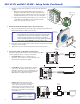
z Digital Input port — Connect a switch
or sensor to this port to control other
devices in the room that are connected to
the MLC serial, IR, or relay ports. The port
monitors the high and low states of the
connection between the switch or sensor
and the connected device. For the voltage
thresholds, a voltage below 1.0 VDC is
considered logic low, and a voltage above
1.5 VDC, logic high. When a threshold
between the states is crossed (from high
to low and vice versa), the selected action
occurs.
By default, this port is configured with a
+5 VDC pull-up resistor for use with basic
non-powered switches. If the device being
connected has its own power source,
configure the port to disable the pull-up
mode (see the configuration program
help file for port setup procedures). To
wire this port, see the example above.
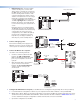
5. Connect and apply power.
Connect the included power supply to the
MLC Pwr connector as shown at right, then
connect power to all devices in the system.
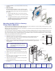
6. Connect the MLC to the computer.
Use either of the following methods:
z Connect a USB A-to-USB mini B cable
between the USB configuration
port on the MLC side panel and a USB
port on your computer as shown at
right; or
z Wire an RS-232 cable to the provided
3-pole connector and connect it
between the MLC Host/Config port
and the computer serial port, as
shown below.
RELAYS
N/O
PWR
12 V
0.4 A max
HOST/
CONFIG
DIGITAL
INPUT
+
Tx
Rx
1
Tx
Tx/
IR
1
2
C
12
R
PORT A
RS-232
PORT B
IR/ S
MLC 62 RS EU or MK
Rear Panel
To RS-232 Port on Computer
or Control System
9-pin HD
Connector
Ground
Rx
Receive
Transmit
Tx
3
Transmit (Tx)
Receive (Rx)
2
Ground
5
5
1
9
6
7. Congure the MLC buttons and ports (see the MLC 60 Series Configuration Program Help File for the procedures).
a. Load and install the configuration software to your computer from the Extron website or the provided DVD.
b. Obtain device drivers. Drivers for the devices that will be connected to the MLC rear panel IR and serial ports can be
obtained from the provided MLC software DVD or downloaded from the Extron website at www.extron.com. You
can also obtain them using the configuration software if an Internet connection is available.
c. Upload the configuration to the MLC.
3
RELAYS
N/O
PWR
12 V
0.4 A max
HOST/
CONFIG
DIGITAL
INPUT
+
Tx
Rx
1
Tx
Tx/
IR
1
2
C
12
R
PORT A
RS-232
PORT B
IR/ S
Ground
Digital Input
MLC RS EU or MK Rear Panel
Two-position Switch
SECTION A–A
A
A
Power Supply
Output Cord
Ridges
Smooth
MLC RS EU or MK
Rear Panel
RELAYS
N/O
PWR
12 V
0.4 A max
HOST/
CONFIG
DIGITAL
INPUT
+
Tx
Rx
1
Tx
Tx/
IR
1
2
C
12
R
PORT A
RS-232
PORT B
IR/ S
Ground
12 VDC Input
Ground all devices.
USB Cable
Type A
USB
Mini Type B
USB
USB 1
PC
USB A
Ports
MLC 62 RS EU or MK
Left Side Panel