
Setup Guide Owner's manual
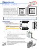

Product Category
IMPORTANT:
Go to www.extron.com for the
complete user guide and installation
instructions before connecting the
product to the power source.
MLC 60 Series • Setup Guide
for the MLC 62 RS EU and the MLC 62 RS MK
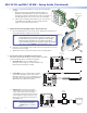
The Extron MLC 62 RS EU and the MLC 62 RS MK
are keypad controllers for use in classrooms and
meeting facilities. The EU model attaches to a
single size European electrical junction box with a
60 mm mounting center; the MK model mounts to
a single size MK junction box. The controllers have
backlit soft touch buttons and can control common
AV functions, including power, input switching, and
volume. Both models provide RS-232 serial and IR
ports for universal display control. A digital input
and two relays enable monitoring and controlling
of other devices in the room. Both models have
six-button and eight-button options.
NOTES: • Installation and service must be performed by authorized personnel only.
• For full installation, configuration, and operation details, see the MLC 60 Series User Guide, available at
www.extron.com.
Installation Steps
1. Prepare the installation site.
The MLC 62 EU and MK controllers can be installed in a
standard EU or MK one-gang electrical wall box:
a. Install the electrical box, following the instructions
provided with it.
CAUTION: Ensure that the junction box is
properly grounded.
b. Prepare and pull the cables through the electrical
box.
2. (Optional) Change the faceplate and buttons as needed.
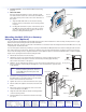
a. Remove the faceplate from the MLC module as follows:
i. On the right and left edges of the faceplate are two pairs of slots, into
which two small tabs on either side of the MLC fit. Insert the flat end
of a small screwdriver into each side slot (as shown at right) and press
inward until the tab is released from its slot.
ii. Lift the faceplate off the MLC circuit board.
b. If desired, replace the buttons in the faceplate as follows:
i. From the front of the faceplate, press the button membrane to be
replaced backward through its faceplate openings until it comes free.
If replacing the faceplate, repeat this step until all the buttons are
removed.
ii. On the back of the faceplate, set the new button membrane at the
desired location, with the two pegs in the upper-left and lower-right
corners of the membrane in the faceplate holes at opposite corners of the
row (see the illustrations at left and at right). Press the pegs and buttons
of the membrane into the faceplate.
iii. Repeat step 2 b as needed.
1
Extron
VOLUME
DISPLAY
ON
OFF
VIDEO
PC
MUTE
LAPTOP
Extron
VOLUME
DISPLAY
ON
OFF
LAPTOP MUTE
PC VIDEO
MLC 62 RS EU
MLC 62 RS MK
Rear Panel
Left Side Panel
RELAYS
N/O
PWR
12 V
0.4 A max
HOST/
CONFIG
DIGITAL
INPUT
+
Tx
Rx
1
Tx
Tx/
IR
1
2
C
12
R
PORT A
RS-232
PORT B
IR/ S
Peg
Peg
Slot
VOLUME
DISPLAY
PC
VIDEO
OFF
ON
MUTE
LAPTOP
MUTE
LAPTOP
Pegs (2)
Button
Membrane