
User Guide Owner's manual

VOL/
MUTE
+ 10V
3
6
4
1
2
5
5
2
6
1
3
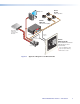
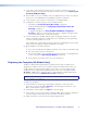
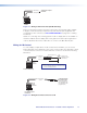
Figure 4. MLC 52 RS MK and MLC 52 RS MK VC Rear Views
ON
PC
OFF
VCR
DV D
DOC
CAM
VOL/
MUTE
+ 10V
1
6
2
3 4
5
ON
PC
OFF
VOL
VOL
1
3
2
6
5
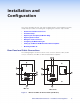
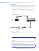
Figure 5. MLC 52 RS EU and MLC 52 RS EU VC Rear Views
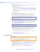
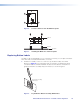
a IR Learner/Transmitter — These sensors allow for IR control of the MLC and for
IR Learning. The two LEDs (one for transmitting, one for receiving) send and receive
IR signals, enabling the MLC to learn commands and clone configurations from
another MLC 52. The IR remote control of the display device must be pointed directly
at these LEDs for best results.
The MLC can “learn” IR commands in order to control the display device. IR Learning
of device control codes is necessary only if there are no RS-232 codes available
for that device or if you need to customize the driver (see Configuring Using IR
Learning on page 18 for the IR Learning procedure).
You can also perform IR learning via the MLC 52 configuration software (see the
MLC 52 Configuration Program help file for the procedure).
b Enable Macro LED — The LED located immediately above or to the right of the four
green IR LEDs is labeled E, for Enable Macro. This LED lights amber when you place
a button in macro mode (see Setting Up Button Macros Using IR on page 20).
MLC 52 RS MK VC
MLC 52 RS MK
MLC 52 RS EU VC
MLC 52 RS EU
MLC 52 MediaLink Controllers • Installation and Configuration 7