
Installation User guide


5-17
MLC 226 IP Series • SIS Programming and Control
PRELIMINARY
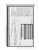
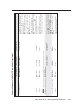
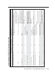
Command/response table for SIS commands (continued)
Command ASCII (Telnet)
(host to switcher)
URL Encoded (Web)
(host to switcher)
Response
(switcher to host)
Additional description
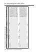
Digital I/O data port (pin 1 of the 9-pin D connector, the Power Sense port on the bottom panel, or the dedicated Digital I/O ports)
confi guration and use
N
An input voltage below 2.0 VDC is considered to be logic low. An input voltage above 2.8 VDC is considered to be logic high. These thresholds are not adjustable.
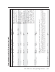
Set the input/output (I/O)
mode
24
X22#
*
X4)
[
X22#
%2A
X4)
%5B Iom
X22#
*
X4)]
Set the input/output mode (
X4)
) for a
specifi c port (
X22#
).
X22#
=
1 = rear panel Host Control port (9-pin D
connector) Digital I/O port 1
2 = Pwr Sns pin on the Display RS-232/IR
port Digital I/O port 2
3 = Digital I/O port 3
X4)
=
0 = input (default)
1 = output
2 = input and pull-up resistor
3 = output and pull-up resistor
8 = power sensor (used only with an Extron
Display Power Sensor connected to the
MLC’s Pwr Sns port).
N
When set for input with pull-up resistor (
X4)
= 2), the digital input can be triggered by an external switch. When the
switch closes, the voltage drops from 5 V to 0 V.
When set for output with pull-up resistor, the MLC’s digital I/O port can drive devices such as relays and LEDs.
When set for power sensor, the input state is triggered when the optional Display Power Sensor connected to the power
sense port detects a state change.
View the digital I/O mode
X22#
[
X22#
%5B
X4)]
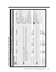
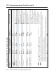
Pulse the digital I/O state
14
X22#
*3*
X6#
]
X22#
%2A3%2A
X6#
%5D Sio
X22#
*
X4# ]
Briefl y change the I/O state.
X6#
= Pulse time in 20 ms per count. If
this parameter is missing or = 0, then pulse
length = default (25 = 500 ms).
65535 (1310 s) = max. pulse time.
X4#
= I/O state:
0 = off
1 = on
N
This and the following three commands are valid only when the port is in output mode or in output with pull-up mode.
Toggle the I/O state
14
X22#
*2]
X22#
%2A2%5D Sio
X22#
*
X4#
]
Switch the input/output state from on to off
or from off to on.
Set the I/O state to on
14
X22#
*1]
X22#
%2A1%5D Sio
X22#
*1
]
Set the I/O state to off
14
X22#
*0]
X22#
%2A0%5D Sio
X22#
*0
]
View the I/O state
X22#
]
X22#
%5D
X4#]