
Installation User guide


3-3
MLC 226 IP Series • Operation
PRELIMINARY
Each Display On/Off, Function/Room, and Input button can be set up to perform
several functions, which can be combinations of the following options:
• a driver operation—execute an RS-232 or IR control command that is part of a
device driver (for a projector, VCR, DVD, audio source, etc.)
• a relay operation—turn relays on or off, or toggle or pulse a relay
• a time delay operation—insert delays between executed commands
• a button light operation—change a front panel button’s brightness, color, or
fl ashing
• a digital input/output operation—turn the digital output on or off, toggle it, or
pulse it
• a user-defi ned RS-232 operation—issue a non-driver-associated RS-232
command (one that you programmed separately) via a specifi c port (IR/Serial
Out A, B, C; or the projector control port) or an internal command for the MLC,
itself
By default all buttons illuminate brightly when selected (active), and light dimly
when deselected. The button caps are removable so the button labels can be
changed.
a
Display On/Off buttons — After they have been confi gured, press the On
button to turn the projector or display device on, and press the Off button to
power it off. By default, only one of these two buttons can be selected (active)
at once. Via Global Confi gurator (GC) software, other functions and relays
can be associated with each of these buttons.
b
Function/room control buttons and
c
input selection buttons — Each of
these buttons can be assigned several functions apiece, depending on how
the MLC is set up and what mode is active. Each button can be confi gured to
control the MLC’s relays, execute the IR or RS-232 commands of your choice,
or trigger event scripts and/or port monitoring.
The relays can be used to control items in the room such as a projector lift,
screen motor, or lighting. For details on how the relays operate and can be
confi gured, see the installation instructions in chapter 2 and the confi guration
software information in chapter 4.
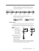
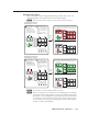
b
Function/room control buttons — These have the same
capabilities as the input selection buttons (
c
), but are
typically used for triggering commands and functions other
than input selection. The F1, F2, and F3 buttons on the
optional IR 402 remote control correspond to these buttons. By
default these three buttons are each associated with a latching
relay, as shown at right. However, any software-based
confi guration, regardless of whether the function buttons are
confi gured or not, overrides the default associations between
these buttons and the relays.
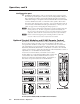
c
Input selection buttons — These buttons, labeled 1 through 6, have the
same capabilities as the function/room buttons (
d
) and can be
confi gured to perform a variety of functions. By
default they are a mutually exclusive group:only
one of these buttons can be selected at a time.
Also, by default each button is associated with
an Extron input switching SIS command (1!, 2!,
3!, and so forth) and bidirectional
communication via the MLC’s MLS RS-232 port.
See the picture at right.
Relay
1
Relay
2
Relay
3
Relay
1
Relay
2
Relay
3
1
2
3
4
5
6
4!
1!
2!
5!
3!
6!
1
2
3
4
5
6
4!
1!
2!
5!
3!
6!