
Installation User guide


Installation, cont’d
MLC 226 IP Series • Installation
2-18
PRELIMINARY
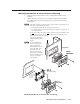
Mounting the MLC to a wall or furniture
1. If you have an MLC 226 IP Series model other than the MLC 226 IP L, remove
the four faceplate attachment screws and remove the original faceplate, if
applicable.
2. If you have a model other than the MLC 226 IP L, attach the optional lectern
mounting faceplate to the MLC with the screws removed in step 1.
3. With power disconnected at the source, insert the MLC into the wall or
furniture.
4. Fasten the MLC and faceplate directly to the furniture or wall using wood
screws.
N
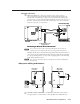
If the MLC (and any accessories such as control modules or an IR Link) is not
mounted to a grounded metal wall box,
• Ground each faceplate directly to an earth ground. Or...
• Tie each faceplate to its circuit board and power supply via a ground pin on
one of the connectors.
Do not tie a product’s faceplate to both a separate earth ground and the circuit
ground (via a connector pin). If you tie a product to two different ground
sources, you may introduce ground loops or other grounding-related problems
into the system.
N
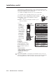
For the installation to meet UL requirements and to comply with National
Electrical Code (NEC), the MLC must be installed in a UL approved junction
box. The end user or installer must furnish the junction box; it is not included
with the MLC. See “Mounting the MLC to an electrical box or mud ring” on
the previous page.
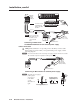
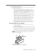
Rack mounting an MLC 226 IP L
1. Attach an MLC 226 IP L to an optional rack mounting faceplate (UCM-RAAP)
with the provided mounting machine screws and nuts.
2. With power disconnected at the source, fasten the MLC and faceplate to the
rack using the supplied machine screws as shown in the following illustration.
Extron
MLC 226 IP L
Extron
UCM-RAAP
DIS
PLAY
1
2
3
4
5
6
VOLUME
CONFI
G
IR
PC
DVD
VCR
LAPTOP
PIC
MUTE
AUTO
IMAGE
ON
OFF
Extron
DOC
CAM
MLC 226 IP
L
Rack mounting the MLC 226 IP L