
Installation User guide


2-13
MLC 226 IP Series • Installation
PRELIMINARY
Intercom connection
g
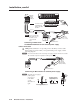
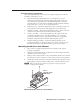
Intercom connectors — This port is used for power, control, and voice
data communication between the MLC and an optional Extron IP Intercom
( IPI 101 AAP or IPI 104 AAP).
Plug one end of a standard, straight through,
CAT 5, CAT 5e, or CAT 6 cable terminated with RJ-45 connectors into this port on
the MLC. Plug the other end of the cable into the Intercom connector on the IP
Intercom’s rear panel, as shown below.
N
A 12" (30.5 cm) CAT 6 cable is included with each IPI. If you choose to
terminate your own cable, the cable must be no longer than 100’ (30.4 m).
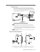
The MLC 226 IP Series controllers that support IPI intercom panels also have
a rear panel, line level, unbalanced audio output port that can be connected
to local, powered speakers or to any audio or paging system. See the wiring
guide in the illustration above.
N
The volume for this audio output can be adjusted via IP Intercom HelpDesk
™
software only.
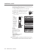
Side panel cabling and features
a
LAN (IP) connector and LEDs — An Ethernet connection can be used on
an ongoing basis to connect and to control the MLC 226 (and the devices
INTERCOM
AUDIO
OUT
IPI 104 AAP, IPI 101 AAP
Rear Panel
MLC 226 IP Series
Rear Panel (left side)
Audio Signal (Tip, +)
Ground (Sleeve, )
To a Speaker, Audio System,
or Paging System
0.2” (5 mm)
MAX.
Connecting an MLC 226 IP to an IP Intercom
INTERCOM
AUDIO
OUT
IPI 104 AAP, IPI 101 AAP
Rear Panel
MLC 226 IP Series
Rear Panel (left side)
Audio Signal (Tip, +)
Ground (Sleeve, )
To a Speaker, Audio System,
or Paging System
0.2” (5 mm)
MAX.
Connecting an MLC 226 IP to an IP Intercom
MLC 226 IP
Left Panel
MLC 226 IP
Right Panel
LAN (IP)
Connector
Side View
1
Reset
Button
Reset
LED
2