
Installation User guide


Installation, cont’d
MLC 226 IP Series • Installation
2-8
PRELIMINARY
N
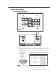
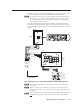
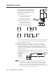
Requirements for setting addresses for IRCM/RCM/ACM/CM control modules
differ depending on how they are connected. If a control module is connected
to the 3-pole connector on an SCP, it can be addressed differently than it would
if connected to the SCP’s 5-pole connector. Refer to the appropriate control
module user’s manual and the SCP 104/226 User’s Manual for instructions
on addressing the control modules.
SCP 226
3 Pole
Connector
SCP 226
C
B
A
3 Pole Connector
C
B
A
C
A
B
C
A
B
C
A
B
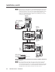
Extron CTLP Cable Color Code:
CM-20BB
Control Module
Address 1
CM-20BB
Control Module
Address 1
CM-20BB
Control Module
Address 1
ACM-Tone
Control Module
Address 2
ACM-Tone
Control Module
Address 2
ACM-Tone
Control Module
Address 2
E
B
A
E
B
A
E
B
A
SCP Communication
+12 VDC
Ground ( ) & Drain Wire
Ground ( ) & Drain Wire
E
D
C
B
A
SCP Communication
Modulated IR (for IR Link)
Control Module Communication
+12 VDC
= White
= Black and Drain Wire
= Violet
= Red
NOTE:
2 SCPs
Maximum
Per System
MLC 226 IP
Bottom Panel
200' (61 m) Max.
to Last Device
C
IRCM, ACM, RCM
VOLUME
SCP 226
IR
DISPLAY
Extron
1
2
3
4
5
6
ON
OFF
PIC
MUTE
AUTO
IMAGE
VCR
DOC
CAM
PC
LAPTOP
DVD
VOLUME
SCP 226
IR
DISPLAY
Extron
1
2
3
4
5
6
ON
OFF
PIC
MUTE
AUTO
IMAGE
VCR
DOC
CAM
PC
LAPTOP
DVD
CM/IR/SCP
A B C D E
+12V OUT
GROUND
CONT MOD
IR IN
SCP COM
TONE CONTROL
BASS TREBLE
MAX/
MIN
TONE CONTROL
BASS TREBLE
MAX/
MIN
TONE CONTROL
BASS TREBLE
MAX/
MIN
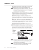
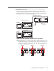
Connections to SCP 226 control panels and control modules without an
IR signal repeater
N
The control module(s) connected via an SCP’s 3-pole connector must be the
same models set to the same DIP switch addresses as the control modules
connected directly to the MLC. For example, if an IRCM-VCR and a CM-5BB
are connected to the MLC’s port, each SCP should have an IRCM-VCR and a
CM-5BB (and not other models) connected to its 3-pole connector.