
Installation User guide


2-7
MLC 226 IP Series • Installation
PRELIMINARY
the MLC is set up) to control VCRs, DVD players, tape decks, a projector lift,
or screen control. Refer to the appropriate device’s user’s manual.
N
If outside factors such as fl uorescent light interfere with and affect the function
of the MLC, you can disable IR control of the MLC. Using a special function
SIS command (65#), you can turn off the MLC’s ability to receive IR signals
from IR signal repeaters and SCPs.
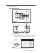
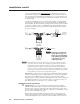
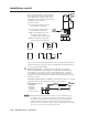
The control modules, IR signal repeater, and SCPs can be daisy chained, as
shown in the following diagram. Extron Comm-Link (CTL and CTLP) cable
is recommended for these connections. Use the following diagrams as wiring
guides.
MLC 226 IP
Bottom
Panel
CM/ IR/SCP
A B C D E
+12V OUT
GROUND
CONT MOD
IR IN
SCP COM
D
B
A
E
D
C
B
A
SCP communication (IR)
Modulated IR
(from IR Link)
Ground ( )
IRCM, ACM, RCM
+12 VDC
C
B
A
Maximum =
2 SCPs
Per System
Maximum =
4 Control
Modules
(4 module
addresses)
Maximum =
1 IR Link
Ground ( )
IRCM/ACM/RCM
+12 VDC
Ground
and Drain
+12 VDC
DVD & VCR CONTROL
PLAY NEXT/FWD PAUSE STOP
TUNER
Tx
PREV/REW
ENTER
TITLE MENU
TV/VCR
DVD VCR
SCP 226
IR Link
SIGNAL
IR LINK
DISPLAY
SCP 226
1
2
3
4
5
6
VOLUME
CONFIG
IR
ON
OFF
VCR
DVD
DOC
CAM
PIC
MUTE
AUTO
IMAGE
MUTE
LAPTOP
PC
200' (61 m) Max.
to Last Device
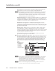
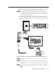
Basic connections to an SCP, control module, and IR signal repeater
N
The maximum total distance between the MLC 226 and a connected device is
200’ (61 m).
N
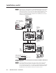
This port provides up to 12 VDC for powering the SCP control pad or other
devices. The automatic current protection circuit for this port limits the draw to
0.5 amperes.
N
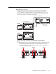
SCP control pads or control modules (CM, IRCM, ACM, RCM) used with the MLC
are affected by front panel security lockout (executive mode) status changes.