
Installation User guide


Installation, cont’d
MLC 226 IP Series • Installation
2-6
PRELIMINARY
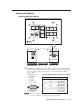
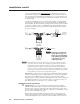
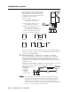
Connect a cable between the right three poles of the Display port and an
optional Extron Display Power Sensor. The Power Sensor can be used to let
the controller know when the projector/display is on or off. If these pins are
not connected to a Power Sensor, the Pwr Sns and Ground pins can be used
for digital input.
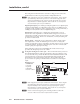
Use the following illustrations as a wiring guide. Wiring varies depending
on the projector/display model. In most cases the drivers are bidirectional,
but sometimes only the transmit (Tx) and ground connections will be needed
for projector/display control. For bidirectional RS-232 communication, the
transmit, ground, and receive pins must be wired at both the MLC and the
projector or display.
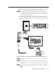
MLC 226 IP
Bottom Panel
DISPLAY
RS-232/IR
Tx/IR
Rx
GROUND
PWR SNS
GROUND
+12V OUT
Tr ansmit (Tx)
Receive (Rx)
Ground ( )
To a
projector
or display
+12VDC
Ground ( )
Power
sense
Sleeve ( )
Ring
(signal)
Tip (+12 V)
3.5 mm Stereo Plug
To an Extron
Power Sensor
(60-271-01)
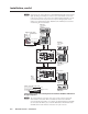
MLC 226 IP
Bottom Panel
DISPLAY
RS-232/IR
Tx/IR
Rx
GROUND
PWR SNS
GROUND
+12V OUT
Tr ansmit (Tx)
Receive (Rx)
Ground ( )
To a
projector
or display
Ground ( )
Digital Input
Digital Input
N
Maximum distances from the MLC to the device being controlled may vary
up to 200 feet (61 m). Factors such as cable gauge, baud rates, environment,
and output levels (from the MLC and the device being controlled) all affect
transmission distance. Distances of about 50 feet (15 m) are typically not a
problem. In some cases the MLC may be capable of transmitting and controlling
a given device via RS-232 up to 250 feet (76 m) away, but the RS-232 response
levels of that device may be too low for the MLC to detect.
Digital input — The power sense (Pwr Sns) pin and the Ground pin together
can act as a digital input port if confi gured that way via Global Confi gurator.
This allows for an additional way to trigger events or functions (such as
triggering relays, issuing commands, or sending an e-mail). When confi gured
as a digital input, this port is in one of two states: 1 (on, high) or 2 (off, low).
Threshold voltages are <2.0 VDC = low, >2.8 VDC = high.
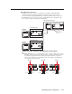
Additional control connections
b
CM/IR/SCP port — You can connect up to four Extron control modules
(IRCMs, ACMs, RCMs, CMs), one Extron infrared signal repeater (IRL 20 or
IR Link), and/or up to two Extron SCP 226 control pads to this port to allow
remote control of the MLC 226 controller or other items. A maximum of seven
devices can be connected to this port.
The SCP 226 replicates the MLC’s front panel controls. The SCP 226 and
the IR signal repeater can receive IR signals from an optional IR 402 remote
control and send them to the controller. Control modules can be used (once
N
Each projector or display may
require different wiring. For
details, refer to the manual that
came with the projector/display
or the Extron device driver
communication sheet.
N
Each projector or display may
require different wiring. For
details, refer to the manual that
came with the projector/display
or the Extron device driver
communication sheet.