
Installation User guide


2-5
MLC 226 IP Series • Installation
PRELIMINARY
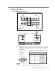
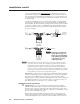
Bottom/rear panel and cabling
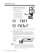
MLC 226 IP Rear Panel
MLC 226 IP Bottom Panel
HOST
CONTROL
R
1=D INPUT I/O
2=Tx 3=Rx 5=GND
38400, N, 8, 1
PRESS TAB WITH
TWEEKER TO REMOVE
INTERCOM
AUDIO
OUT
LAN
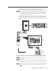
MLC 226 IP Rear Panel
A B C D E
DISPLAY
RS-232/IR RS-232 12V
CM/IR/SCP
A B C D E
MLS PWR
AB
Tx/IR
Rx
GROUND
PWR SN S
GROUND
+12V OUT
Rx
Tx
GROUND
GROUND
+12V IN
+12V OUT
GROUND
CONT MOD
IR IN
SCP COM
NORMALLY OPEN
1 2
COMMON
COMMON
COMMON
GROUND
Tx/IR
Tx/IR
Tx/IR
GROUND
GROUND
A
RELAYS
IR/SERIAL OUT
3 4
B
5 6
CA BC
5 6 4 1 2 3
7
a
Display control (Display RS-232/IR) and display power sensor port
b
CM/IR/SCP port
c
Relay ports (24 V, 1 A)
d
IR/Serial Output ports
e
MLS connector
f
PWR (power) connector
g
Intercom connectors
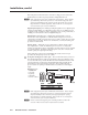
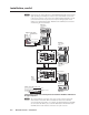
Projector/display connections
a
Display control (Display RS-232/IR) port (-5 VDC to +5 VDC) —
Connect a cable between the projector or display and the left three poles of
this 3.5 mm direct insertion captive screw connector for bidirectional RS-232
control. Alternatively, the Tx/IR and Ground pins can be used for one-way
infrared signal output. From this port, commands from a projector driver or
user-defi ned command strings entered via Global Confi gurator can be sent to
the display device.
Projector
Panel
MLC 226 IP
Bottom Panel
DISPLAY
RS-232/IR
Tx/IR
Rx
GROUND
PWR SNS
GROUND
+12V OUT
Ground ( )
Receive (Rx)
Tr ansmit (Tx)
Ground ( )
Receive (Rx)
Tr ansmit (Tx)
Bidirectional