
Installation User guide


2-3
MLC 226 IP Series • Installation
PRELIMINARY
Panels and Cabling
Host/Confi g port cabling
DISPLAY
MLC 226 IP
1
2
3
4
5
6
VOLUME
CONFIG
IR
ON
OFF
PIC
MUTE
MUTE
DOC
CAM
VCR
DVD
LAPTOP
AUX
VIDEO
PC
AUTO
IMAGE
HOST
CONTROL
R
1=D INPUT I/O
2=Tx 3=Rx 5=GND
38400, N, 8, 1
PRESS TAB WITH
TWEEKER TO REMOVE
INTERCOM
AUDIO
OUT
LAN
2 1
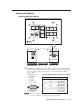
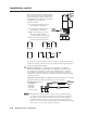
MLC 226 IP Front Panel
ML
C
22
6
IP Rear Panel
a
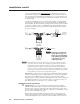
Rear panel Host Control port — For MLC confi guration and control, connect
a Windows
®
-based PC or an RS-232 control system to the MLC via this female,
9-pin D connector. This connector also has one pin designated for digital
input/output.
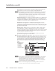
RS-232 protocol:
• 38400 baud
• 1 stop bit
• no parity
• 8 data bits
• no fl ow control
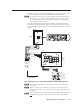
DB9 Pin Locations
Female
51
96
N
Extron recommends confi guring and controlling the MLC via the LAN
connector. Ethernet connections are faster and more reliable.
Pin
RS-232 function
Description
1 Digital I/O Digital input/output
2 Tx Transmit data
3 Rx Receive data
4 — No connection
5 Gnd Signal ground
6 — No connection
7 — No connection
8 — No connection
9 — No connection
Pin
RS-232 function
Description
1 Digital I/O Digital input/output
2 Tx Transmit data
3 Rx Receive data
4 — No connection
5 Gnd Signal ground
6 — No connection
7 — No connection
8 — No connection
9 — No connection
The pin assignments of this connector are as follows:The pin assignments of this connector are as follows: