
Installation User guide


6-11
MLC 226 IP Series • Special Applications
PRELIMINARY
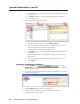
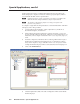
e. Repeat steps 13b through 13d to select a button light setting for the other
(second) button release.
14. To each toggle action, add a command to switch the input of the projector or
switcher.
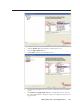
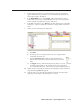
15. Complete the rest of the confi guration as described in the MLC 226 IP Series
Setup Guide and in chapter 4 of this manual: confi gure all control ports for IR
or RS-232 communication and select device drivers, confi gure the rest of the
buttons (including IRCM-DV+ buttons). Confi gure e-mail settings and set
scheduling as appropriate, then save the project and build and upload the
confi guration to the MLC.
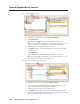
Controlling Two Display Devices
There are many ways you can use the MLC to control dual projectors or panel
displays. One way is to use the Display On/Off buttons to control the fi rst
projector and confi gure two function buttons to act as On and Off buttons for the
second projector.
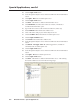
For another way to control two projectors, set up the Display On/Off buttons
to each control a different projector. The MLS port is typically used to control a
connected Extron switcher. However, you can disable the MediaLink switcher
support mode, then add a driver to that port. This same general procedure
can be used to make the MLC control any other device that uses RS-232 serial
communication for control.
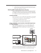
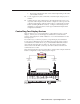
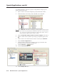
The following illustration shows how the MLC is wired for this example and which
button is confi gured to control which projector and port.
MLC 226 IP
Bottom Panel
MLC 226 IP
Front Panel Buttons
PROJ
1
PROJ
2
DISPLAY
A B C D E
DISPLAY
RS-232/IR RS-232 12V
CM/IR/SCP
A B C D E
MLS PWR
AB
Tx/IR
Rx
GROUND
PWR SN S
GROUND
+12V OUT
Rx
Tx
GROUND
GROUND
+12V IN
+12V OUT
GROUND
CONT MOD
IR IN
SCP COM
NORMALLY OPEN
1 2
COMMON
COMMON
COMMON
GROUND
Tx/IR
Tx/IR
Tx/IR
GROUND
GROUND
A
RELAYS
IR/SERIAL OUT
3 4
B
5 6
CA BC
Tx Rx Rx Tx
To projector 1:
Sony
VPL-PX20
To projector 2:
Sony
VPL-PX30