
Installation User guide


5-35
MLC 226 IP Series • SIS Programming and Control
PRELIMINARY
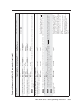
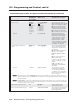
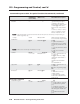
Command/response table for special function SIS commands, continued
Command ASCII
Command
(host to MLC)
Response
(MLC to host)
X?
values
and additional descriptions
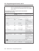
Button associations (virtual mapping) for an IRCM-DV+
By design an IRCM-DV+ can be assigned paired module addresses (by DIP switch) of either 1&2 or 3&4 only. It cannot
be assigned to addresses 2&3 or 1&4. The odd-numbered module address (1 or 3) is reserved for DVD control, the even-
numbered module address (2 or 4) is for VCR control. The address DIP switches must be set in order for the MLC to
recognize and reserve memory space for the module. Refer to the Control Modules User’s Manual.
To use an optional IRCM-DV+ with an MLC 226 IP, you need to associate the DVD portion of this module with an
MLC input selection butto, and also associate the VCR portion with a different MLC input selection button. The
associated button must be selected (pressed) in order to activate and use the VCR portion or the DVD portion of the
module. You cannot activate both parts (VCR and DVD) at the same time. If you do not associate (map) the IRCM-
DV+’s addresses (1&2 or 3&4) with MLC buttons, you cannot activate and use either the DVD or the VCR part of the
IRCM-DV+.
N
For MLC 226 Series MediaLink Controllers, you can assign both the DVD and VCR portions of an IRCM-DV+ to the
same input selection button. A and B must both be inputs that are set up for input switching mode (fi rmware control)
via Global Confi gurator.
Here is how to determine the value of
X? for the following commands:
Button to
associate the
VCR half
(even address,
2 or 4) with
Button to
associate the
DVD half
(odd address,
1 or 3) with
A
(A x 16) + (B) =
B
X?
X? is a decimal
number from
000 to 101.
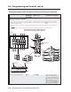
IRCM-DV+ address 2, address 1 button association
Associate MLC’s buttons w/IRCM-DV+
24
Associate specifi c MLC 226 IP
input selection buttons with the
VCR and DVD halves of the
IRCM-DV+ that has DIP switch-
based addresses of 1 and 2.
X?
can be from 0 to 101.
X?
*25# DVA_VMap*
X?]
Example:
52*25# DVA_VMap*052 Associate the MLC’s input
4 button with IRCM-DV+
address 1 (DVD functions) and
the MLC’s input 3 button with
IRCM-DV+ address 2 (VCR
functions). See the illustration
at left.
Button to
associate the
VCR half
(even address,
2) with
Button to
associate the
DVD half
(odd address,
1) with
3
= (3 x 16) + (4) = 52
4
X?
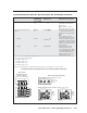
IRCM-DV+ address 4, address 3 association
Associate MLC’s buttons w/IRCM-DV+
24
Associate MLC 226 IP buttons
with the VCR & DVD parts of an
IRCM-DV+ that has DIP switch-
set addresses of 3 and 4.
X?
*26# DVB_VMap*
X?]
IRCM-DV+ activation
Force an IRCM-DV+ to activate one half (DVD or VCR) or to turn off
X?
*
Y?
*24# DV_Force*
X?
*
Y? X?
= DIP switch address (1, 2, 3,
or 4) of the IRCM-DV+.
For
Y?
:
0 = turn off IRCM-DV+,
1 = force the DVD half on (make
it active),
2 = force the VCR half on.
N
This command overrides the 25# and 26# commands listed above.
N
This command also does not require each half of the IRCM-DV+ to be
associated with an input button.
Read an IRCM-DV+’s status
X?
*24#
Y?
See the
X?
and
Y?
values above.