Installation Manual DISPLAY ON PIC MUTE OFF DVD VCR 1 4 2 5 3 6 DOC CAM LAPTOP PC VOLUME AUTO IMAGE IR CONFIG Left Side MLC 226 IP Right Side Front INTERCOM R HOST CONTROL AUDIO OUT LAN 1=D INPUT I/O 2=Tx 3=Rx 5=GND 38400, N, 8, 1 PRESS TAB WITH TWEEKER TO REMOVE CM/IR/SCP RELAYS NORMALLY OPEN A B C IR/SERIAL OUT Rx Tx GROUND GROUND +12V IN Tx/IR GROUND 5 6 C Tx/IR GROUND B Tx/IR GROUND A B C D E RS-232/IR 3 4 COMMON DISPLAY 1 2 A COMMON A B C D E COMMON T x/
Precautions Safety Instructions • English Warning This symbol is intended to alert the user of important operating and maintenance (servicing) instructions in the literature provided with the equipment. Power sources • This equipment should be operated only from the power source indicated on the product. This equipment is intended to be used with a main power system with a grounded (neutral) conductor. The third (grounding) pin is a safety feature, do not attempt to bypass or disable it.
Table of Contents Chapter One • Introduction ...................................................................................................... 1-1 About the MLC 226 IP Series MediaLink™ Controllers ......................................... 1-2 MLC 226 IP Series features ....................................................................................................... 1-2 Controlling other devices.....................................................................................................
Table of Contents, cont’d Front Panel Security Lockout (Executive Mode) ..................................................... 3-7 Enabling and disabling front panel lockout via the embedded Web pages and the front panel .......................................................................................................................... 3-7 Using the Web pages .......................................................................................................... 3-8 Using the front panel ............
GlobalViewer™ Web Pages..................................................................................................... 4-29 Control ............................................................................................................................... 4-30 Monitor .............................................................................................................................. 4-31 Schedule ............................................................................................
Table of Contents, cont’d Appendix B • Firmware Updates ...........................................................................................B-1 Determining the Firmware Version ................................................................................B-2 Using the Global Configurator software ...............................................................................B-2 Using a Web browser ......................................................................................................
1 Chapter One Introduction About the MLC 226 IP Series MediaLink™ Controllers How the MLC 226 IP Series Controllers Work: MLC Components and Interactions PRELIMINARY MLC 226 IP Series
Introduction About the MLC 226 IP Series MediaLink™ Controllers The Extron MLC 226 IP Series MediaLink Controllers are capable of controlling a projector and various other items such as lights, a projector lift, or a screen motor. Throughout this manual they are referred to as the MLC 226, MLC, or controller.
TCP/IP Network Help Desk PC OR NIT MO ER INT CO LE M MED LOW SH PU TO EC TO AU E IMAG R OJ PR TE VO LU R MU LP HE SK DE 3 6 LK MIN AD E FIC OF 4 104 IPI 3 P C ML PTOP C DOM CA UR SEC 2 1 PC G CO ME D 2 5 1 4 LA F OF ON Projector Control VC TA B LA ITY DV TO L VE HIGH NFI 6 IP 22 AA Extron IPI 104 AAP Intercom IR Extron MLC 226 IP AAP RGBHV Video MediaLink Controller S-video UT TP D OU FT LE IFIE PL AM HT RIG Projector 12V Tx Rx IR C AU 2 DIO L
Introduction, cont’d How the MLC 226 IP Series Controllers Work: MLC Components and Interactions Unlike the Extron MediaLink Controller (MLC 206 Series), the MLC 226 IP Series requires and uses event files to perform all functions except basic input switching and volume control. The event files define, monitor, and govern how an MLC 226 IP Series controller works. Below is an example diagram of how the MLC interacts with accessories, event scripts, drivers, ports, and input and output devices.
2 Chapter Two Installation UL/Safety Requirements Installing or Replacing Button Labels Panels and Cabling Resetting the Unit Pinout Guide Mounting the MLC PRELIMINARY MLC 226 IP Series
Installation UL/Safety Requirements The Underwriters Laboratories (UL) requirements listed below pertain to the safe installation and operation of a MediaLink™ Controller (MLC). 1. Do not use the MLC near water or expose it to liquids. W To reduce the risk of fire or electric shock, do not expose this apparatus to rain or moisture. 2. Clean the MLC only with a dry cloth. 3.
Panels and Cabling Host/Config port cabling DISPLAY ON OFF VOLUME PIC MUTE MUTE AUTO IMAGE VCR DVD AUX VIDEO 1 4 2 5 3 6 DOC CAM LAPTOP PC IR CONFIG PRELIMINARY MLC 226 IP MLC 226 IP Front Panel 1 2 INTERCOM R HOST CONTROL AUDIO OUT LAN 1=D INPUT I/O 2=Tx 3=Rx 5=GND 38400, N, 8, 1 PRESS TAB WITH TWEEKER TO REMOVE MLC 226 IP Rear Panel a Rear panel Host Control port — For MLC configuration and control, connect a Windows®-based PC or an RS-232 control system to the MLC via this
Installation, cont’d The front panel 2.5 mm mini stereo connector Config port serves the same RS-232 function as this rear panel port but is independent from it. N Both configuration ports require 38400 baud communication. This is a higher speed than many other Extron products use. The Global Configurator (GC) software automatically sets the connection for the appropriate speed.
Bottom/rear panel and cabling MLC 226 IP Rear Panel INTERCOM AUDIO OUT C RELAYS Tx/IR GROUND 5 6 5 Tx/IR GROUND COMMON 3 4 B A CM/IR/SCP RS-232/IR 4 Tx/IR GROUND A B C D E DISPLAY 1 2 COMMON A B C D E COMMON 3 +12V OUT GROUND CONT MOD IR IN SCP COM 2 + 1 2 V OUT Tx/IR Rx GROUND P W R SNS GROUND 1 PRESS TAB WITH TWEEKER TO REMOVE A B C NORMALLY OPEN IR/SERIAL OUT 6 PRELIMINARY LAN 1=D INPUT I/O 2=Tx 3=Rx 5=GND 38400, N, 8, 1 Rx Tx GROUND GROUND +12V IN R 7 HOST CONTR
Installation, cont’d Connect a cable between the right three poles of the Display port and an optional Extron Display Power Sensor. The Power Sensor can be used to let the controller know when the projector/display is on or off. If these pins are not connected to a Power Sensor, the Pwr Sns and Ground pins can be used for digital input. Use the following illustrations as a wiring guide. Wiring varies depending on the projector/display model.
the MLC is set up) to control VCRs, DVD players, tape decks, a projector lift, or screen control. Refer to the appropriate device’s user’s manual. N If outside factors such as fluorescent light interfere with and affect the function of the MLC, you can disable IR control of the MLC. Using a special function SIS command (65#), you can turn off the MLC’s ability to receive IR signals from IR signal repeaters and SCPs.
Installation, cont’d N Requirements for setting addresses for IRCM/RCM/ACM/CM control modules differ depending on how they are connected. If a control module is connected to the 3-pole connector on an SCP, it can be addressed differently than it would if connected to the SCP’s 5-pole connector. Refer to the appropriate control module user’s manual and the SCP 104/226 User’s Manual for instructions on addressing the control modules.
MLC 226 IP DV+ connections The MLC 226 IP DV+ consists of an MLC 226 IP controller and an IRCM-DV+ installed in a high-impact plastic faceplate. The wiring is the same as in the previous diagram, except the IRCM-DV+ is cabled to the MLC at the factory and the IRCM-DV+ is the only type of control module that may be connected to each SCP’s 3-pole connector. See the following diagram.
Installation, cont’d All relays are normally open. Normally Open (5) Common Normally Open (6) Common These relays are normally open by default. They will return to an open state if power is removed from the controller.
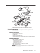
For infrared (IR) output (0 to +5 VDC), wire an IR Emitter (2 emitters, maximum, per port) as shown below for a modulated or demodulated signal and ground. For specific information about wiring more than one IR Emitter per port or about extending the length of the Emitter wires, refer to the Extron IR Emitter Installation Guide, part #68-808-01. N If installing two IR Emitters per port, wire them in series, not in parallel.
Installation, cont’d INPUT 1 INPUT 2 VIDEO INPUT 3 R-Y VIDEO Y INPUT 4 R-Y Y INPUT 5 INPUT 6 RGB R H/ HV R H/ HV R H/ HV R H/ HV G V G V G V G V YUV VIDEO R-Y MONO AMPLIFIED OUTPUT S-VIDEO Y COMM 4 ohm 8 ohm 70V Y 0.2A 50/60 Hz B-Y C C B-Y C B-Y B B B B B-Y AUX/MIX EFFECTS L R L R L R L R L R L SEND R .
Intercom connection g Intercom connectors — This port is used for power, control, and voice data communication between the MLC and an optional Extron IP Intercom (IPI 101 AAP or IPI 104 AAP). Plug one end of a standard, straight through, CAT 5, CAT 5e, or CAT 6 cable terminated with RJ-45 connectors into this port on the MLC. Plug the other end of the cable into the Intercom connector on the IP Intercom’s rear panel, as shown below.
Installation, cont’d connected to it) in an Ethernet network. Plug a cable into this RJ-45 socket, and connect the other end of the cable to a network switch, hub, router, or PC connected to an Ethernet LAN or the Internet. • For 10Base-T (10 Mbps) networks, use a Cat 3 or better cable. • For 100 Base-T (max. 155 Mbps) networks, use a Cat 5 cable. You will also need to configure this port before using it. LAN RJ-45 Port Activity LED — This yellow LED blinks to indicate network activity.
Resetting the Unit There are four reset modes (numbered 1, 3, 4, and 5 for the sake of comparison with an Extron IPL product) that are available by pressing the Reset button on the side panel. The Reset button is recessed, so use a pointed stylus, ballpoint pen, or Extron Tweeker to access it. See the following table for a summary of the modes. C Review the reset modes carefully. Using the wrong reset mode may result in unintended loss of flash memory programming, port reassignment, or a controller reboot.
Installation, cont’d Pinout Guide The illustration below summarizes the pin assignments of all of the MLC’s bottom panel connectors that are covered in detail on pages 2-5 to 2-14.
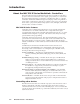
Mounting the MLC to an electrical box or mud ring 1. With power disconnected at the source, insert the MLC into the wall or furniture. 2. Mount the MLC to the wall box or mud ring mounting bracket with the provided machine screws (mounting screws, as shown in the following illustrations). N If the MLC (and any accessories such as control modules or an IR Link) is not mounted to a grounded metal wall box, • Ground each faceplate directly to an earth ground. Or...
Installation, cont’d Mounting the MLC to a wall or furniture 1. If you have an MLC 226 IP Series model other than the MLC 226 IP L, remove the four faceplate attachment screws and remove the original faceplate, if applicable. 2. If you have a model other than the MLC 226 IP L, attach the optional lectern mounting faceplate to the MLC with the screws removed in step 1. 3. With power disconnected at the source, insert the MLC into the wall or furniture. 4.
UL rack mounting requirements 1. Elevated operating ambient temperature — If installed in a closed or multi-unit rack assembly, the operating ambient temperature of the rack environment may be greater than room ambient temperature. Therefore, install the MLC in an environment compatible with the maximum ambient temperature (Tma = +122 °F, +50 °C) specified by Extron. 2.
PRELIMINARY Installation, cont’d 2-20 MLC 226 IP Series • Installation
3 Chapter Three Operation Projector Control Front Panel Features and Operation Optional Control Modules and IR 402 Remote Control Front Panel Security Lockout (Executive Mode) PRELIMINARY MLC 226 IP Series
Operation Projector Control The MLC can control a projector or other display device by using IR or RS-232 control. The MLC must be configured for projector control in one of the following ways before it will send commands to the projector: • An IR or an RS-232 driver file can be installed from a disk, downloaded from the Extron Web site (www.extron.com), or downloaded from Extron using the driver subscription feature within Global Configurator.
Each Display On/Off, Function/Room, and Input button can be set up to perform several functions, which can be combinations of the following options: • a driver operation—execute an RS-232 or IR control command that is part of a device driver (for a projector, VCR, DVD, audio source, etc.
Operation, cont’d Alternatively, the buttons can be reconfigured (via software) to select different inputs and to trigger different commands to be issued. See chapters 4 and 5 for details. Press an input selection button to select the desired audio and video input on the projector or an optional Extron switcher. The button lights brighter and remains lit while an audio-video input is selected. N When these input selection buttons are configured for input switching, there is a default 0.
If the MLC is configured for use with a MediaLink Switcher or for some projectors, the MLC’s LEDs light to indicate volume ranges (with steadily lit LEDs) and minimum/maximum volume limits (with flashing LEDs), as shown in the following diagram. Range-based Volume Adjustment VOLUME VOLUME VOLUME VOLUME VOLUME VOLUME VOLUME Minimum, 0% of Max. Volume 1% to 19% of Max. Volume 20% to 39% of Max. Volume 40% to 59% of Max. Volume 60% to 79% of Max. Volume 80% to 99% of Max. Volume 100% of Max.
Operation, cont’d Configuration port g Config (host control) port — This is a front panel version of the rear panel Host Control port (the 9-pin D connector), and it is independent of that port. This port makes it possible to upload and configure device drivers and also to initiate IR learning via a front panel connection after the MLC has been installed. Connect a Windows-based PC or an RS-232 control system to this 2.5 mm mini stereo-style (tip-ring-sleeve) connector.
The buttons on the optional IR 402 remote duplicate the MLC’s front panel controls and also those of a VCR and a DVD player for normal operation. The IR 402 can also be used to control a MediaLink Switcher. The controller or switcher responds to commands from the IR 402 remote as if the corresponding button or knob were pressed or turned on the controller or switcher.
Operation, cont’d Using the Web pages Using a Web browser, enter the MLC’s IP address and open the MLC’s embedded Web page. If an administrator password has been set and if you are prompted to do so, type in the administrator password. 2. Click on the Configuration tab, which opens to the System Settings page. 3. Select either Off or Disable Front Panel, SCP, Control Modules and IR in the Executive Mode settings area. See the following picture. PRELIMINARY 1.
Using the front panel One or more PINs must be configured before this procedure can be used. See “Preparing the MLC for front panel lockout“ later in this chapter. N Make sure the projector is off before using a PIN to lock the front panel. Locking the Front Panel of an MLC 226 IP Series Controller If the correct PIN is entered, the green Volume LEDs flash and all buttons flash red 3 times, indicating that front panel is locked, then return to the way they were lit before front panel lockout was set.
Operation, cont’d Preparing the MLC for front panel lockout To allow access to front panel changes to specific personnel while the front panel is locked, you can set a user and/or administrator PIN and set which type of PIN, if any, is allowed to unlock the panel. Setting up and enabling or disabling PINs Install and start the Extron Global Configurator (GC) software. See chapter 4. 2. Open an existing GC project or start a new project.
Scheduling front panel lockouts You can set the MLC’s front panel to be automatically locked at certain times and days by setting up a schedule and uploading it to the MLC. Start the Extron Global Configurator (GC) software. See chapter 4. 2. Open an existing GC project or start a new project. Refer to the GC help file or the MLC 226 IP Series Setup Guide for instructions. 3. In the IP Link tab area on the left side of the screen, click on the name of the MLC you want to set up. 4.
PRELIMINARY Operation, cont’d 3-12 6. Type in a name for the schedule that will automatically lock the MLC’s panel. 7. In the Schedule Times area, select the days and hours when front panel lockout should start. 8. Click Next. 9. Set up the front panel lockout action for the MLC. See the illustration on the following page. a. Check the Action check box. b. Select the MLC, itself, from the Subject Ports list. c. Click on Lockout Front Panel in the Available Options list.
Click Add Schedule. The Scheduled Actions Wizard window reappears. 11. Type in a name for the schedule that will automatically unlock the MLC’s panel. 12. In the Schedule Times area, select the days and hours when the front panel should be unlocked. 13. Click Next. 14. Set up the front panel unlock action for the MLC. a. Check the Action check box. b. Select the MLC, itself, from the Subject Ports list. c. Click on Unlock Front Panel in the Available Options list.
PRELIMINARY Operation, cont’d 3-14 MLC 226 IP Series • Operation
4 Chapter Four Software-based Configuration and Control Configuration and Control: an Overview The Basic Steps: A Guide to this Chapter and Other Resources Configuring the MLC for Network Communication Global Configurator Software for Windows® Advanced Configuration Controlling the MLC Customizing the MLC’s Control Web Pages PRELIMINARY MLC 226 IP Series
Software-based Configuration and Control Configuration and Control: an Overview An MLC 226 IP Series controller must be configured before use or it will not be able to control other devices. The MLC 226 IP can be configured and controlled via a host computer attached to the rear panel Host Control port or LAN port, or the front panel Config port. See chapter 2 for pin assignments and other details on the configuration and control ports.
6 Control the MLC and devices connected to it by using the MLC’s embedded Web pages or its GlobalViewer (GV) Web pages. See “Controlling the MLC,” later in this chapter. Configuring the MLC for Network Communication To function together, both the PC and the MLC 226 IP must be configured correctly.
Software-based Configuration and Control, cont’d Configuring the MLC for network communication via Global Configurator software You can configure the controller’s IP address via an IP/Ethernet connection using the Extron Global Configurator (GC) Windows-based software. Read the Global Configurator help file for basic information on using Global Configurator software and setting up a project.
6. After verifying that the IP address change was successful, enter and issue the arp –d command at the DOS prompt. For example: arp –d 10.13.197.9 removes 10.13.197.9 from the ARP table or arp –d* removes all static IP addresses from the ARP table. Configuring the MLC for network communication via a Web browser The default Web pages that are preloaded on the MLC 226 IP are compatible with popular Web browsers such as Netscape Navigator (version 6.0 or higher), Internet Explorer (version 5.
Software-based Configuration and Control, cont’d 5. Set the MLC for the new IP address using either step 5a or step 5b. PRELIMINARY a. Enter the new IP address for the MLC, the corresponding subnet mask, and the gateway address, then click on the Submit button. IP addresses, subnet mask, and e-mail addresses follow standard naming and numbering conventions/protocol. The IP network administrator should provide the IP addresses and subnet mask to be used with this controller.
3. Start Telnet on the PC a. Click the Start menu and select Run. The Run dialog box appears. b. Type telnet, a space, and the default IP address (192.168.254.254) into the Open area, and click OK. Set the MLC for the new IP address by doing one of the following: • Enter SIS command E X1$ CI}, where X1$ is the new IP address (see chapter 5, “SIS™ Programming and Control”) to set the IP address. or • 4. Enter SIS command 1DH} to enable DHCP.
PRELIMINARY Software-based Configuration and Control, cont’d 2. Right-click on Local Area Connection, then select Properties. 3. Select Internet Protocol (TCP/IP) and click on the Properties button. If Internet Protocol (TCP/IP) is not on the list, it must be added (installed). Refer to the Windows user’s manual or the Windows online help system for information on how to install the TCP/IP protocol. 4. Write down the PC’s current IP address and subnet mask below.
6. Click the OK button to save the changes and exit the network setup. Reboot the PC, if required, for the changes to become effective. Plug one end of a Category 5 network/Ethernet crossover cable into the MLC’s Ethernet (LAN) connector. Refer to chapter 2 for RJ-45 LAN connector wiring. Plug the other end of the Ethernet cable into the Ethernet port on the PC. N If a network hub or switch is used between the PC and the MLC 226 IP, use a straight-through Category 5 cable instead of a crossover cable. 7.
Software-based Configuration and Control, cont’d IR Learner™, a free software utility for capturing infrared codes from a handheld IR remote control to create custom drivers for operating IR-controlled devices like the MLC that use IP Link® and GlobalViewer. N Do not change the directory or the name of the directory where the software files are installed by default. Refer to the MLC 226 IP Series Setup Guide for specific information on how to download the software.
• The MLC can be set up to allow configuration access to administrators only, and to prevent other users from making changes to the controller’s settings, events, and drivers. If an administrator password is set for the controller, nonadministrator end users can select inputs and adjust output volume but are prevented from making any other changes using GlobalViewer Web pages. • The unit name is any name (e.g., Room107MLC226IP, Lab1234mlc226IP, ConfRoomSystem, LectureHall8-cntrlr, etc.
Software-based Configuration and Control, cont’d Front Panel allows you to configure and label each front panel button and to associate actions, commands, drivers, and relay functions with the MLC’s front panel buttons. N Failure to configure the On or Off buttons to send their commands upon button release (instead of at the button press) may cause problems with the PIN Mode feature.
PRELIMINARY • miscellaneous settings, including whether to reset button statistics or upload the enhanced Web pages when the configuration is uploaded to the MLC Display power up/power down settings (Power Settings) All the settings in this section affect what happens during display power on/up and power off/down cycles.
Software-based Configuration and Control, cont’d Most projectors do not accept commands during warm up and cool down periods. The next two settings in this area specify the amount of time (0 to 300 seconds in 2-second intervals) for the MLC to wait between issuing a projector power-on or power-off command and when the next input button press can occur. These delays can also be set using special SIS commands (see pages 5-34, and 5-39 through 5-40).
This feature addresses a problem that occurs with some projectors that use range type volume control. When the MLC’s knob controls projector volume, sometimes the MLC sends the volume commands faster than the projector can detect and process them. The projector does not detect some of the volume change commands, resulting in a choppy volume ramp. Encoder scaling gives the programmer the ability to slow the knob down to a speed the projector can handle.
Software-based Configuration and Control, cont’d Configuring an auxiliary switcher An Extron MediaLink Switcher (MLS) or PoleVault switcher (PVS) can be connected to the MLC to expand the number of inputs available to the projector/ display. However, if the MLS or PVS switcher is disabled, the MLS RS-232 port can be used as an auxiliary, bidirectional RS-232 port, just like the Display port. PRELIMINARY To enable and configure an auxiliary switcher, follow these steps: 1.
1. Install and start the Extron Global Configurator (GC) software. See page 4-9. 2. Open an existing GC project or start a new project. Refer to the GC help file or the MLC 226 IP Series Setup Guide for instructions. 3. Click Tools and select Change Device Settings from the drop-down menu. 4. In the Device Settings window, select (click on) the desired MLC in the list that appears on screen. 5. Click Settings and choose Set Administrator Password from the drop-down menu, as shown at right.
Software-based Configuration and Control, cont’d Printing a wiring block diagram Once you have configured a system using Global Configurator, you can generate and print a simple block diagram of what products to wire to which of the MLC’s ports. The diagram includes model names, DIP switch settings for control modules, and the type of communication (IR or RS-232) configured for each port. N This procedure requires Microsoft® Word software. The installer or user must provide that software.
Controlling the MLC You can control the MLC and devices connected to it by using the MLC’s factoryembedded Web pages or its GlobalViewer (GV) Web pages that were created when you uploaded the GC configuration or a customized graphical user interface (GUI). Embedded Web pages The MLC 226 IP features an embedded Web server, which includes factory set Web pages.
Software-based Configuration and Control, cont’d Status These Web pages provide only settings information. Changes must be made via the Configuration Web page or via the Global Configurator software or SIS programming. Personnel who have user access can view these pages but do not have access to configuration pages.
Statistics The Statistics page is mainly for administrators and maintenance personnel. It shows information about system usage: the number of hours the system has been turned on, how many hours the projector lamp has been used, how much time per day and per week the system is turned on, and how many times each button on the MLC has been pressed, either physically or virtually (via configuration software, SIS commands, or event scripts).
Software-based Configuration and Control, cont’d Configuration There are four Configuration Web pages, which only administrators can access: PRELIMINARY • System Settings for IP, date/time, and executive mode (front panel lockout) setting changes N Unit Name is any name (e.g., Room107MLC226IP, Lab1234mlc226IP, ConfRoomSystem, LectureHall8-cntrlr) you use to label this specific MLC. The default is a combination of the product name and part of the hardware address.
• Passwords, where you can change the administrator and/or user passwords • Email Alerts, in which you can specify the Web server’s IP address and domain name, set up SMTP verification credentials, and specify e-mail alert recipients’ addresses and which e-mail file they will be sent N The MLC must first be configured with Global Configurator before e-mail addresses and e-mail file names appear on this page.
Software-based Configuration and Control, cont’d PRELIMINARY • Firmware Upgrade, through which you can locate and load new firmware to the unit N See appendix B, “Firmware Updates,” for instructions on how to update the controller’s firmware. N Save the existing configuration project before replacing the firmware. File Management This Web page allows you to sort by file type (see the Filter by File Extension drop-down box). Personnel with administrator access can view these pages and make changes.
____.cdc files should NOT be deleted. C Event files should NOT be deleted. They are necessary for the controller’s operation. Never delete the main event file (0.evt). You can also view files in subfolders, including those containing GlobalViewer files or IP Intercom files, if they have been installed on the MLC.
Software-based Configuration and Control, cont’d Control • User Mode — The first of the Control Web pages is User Mode, which is a representation of the controller’s front panel buttons, volume control, and any optional control modules (IRCMs, RCMs, ACMs) that are part of the system. Clicking on a button on screen emulates a button press on the corresponding device. This page is accessible to both administrators and users.
• IR Drivers — This Web page lists IR driver files only and allows you to select a file to see and execute the commands stored in them. This page is available only to those logged in with administrator level access. PRELIMINARY N The MLC must first be configured with Global Configurator before this page can be used. An example for a specific IR driver is shown below.
PRELIMINARY Software-based Configuration and Control, cont’d Example of a page for an RS-232 controlled teleconferencing unit connected to the MLC’s IR/Serial Out port B Example of a page for a projector driver 4-28 MLC 226 IP Series • Software-based Configuration and Control
GlobalViewer™ Web Pages The MLC 226 IP controller can be used as part of a network of devices based on Extron IP Link™ technology, such as IP Link interfaces. Global Configurator (GC) is a Windows-based program used for configuring and customizing the Web browserbased GlobalViewer (GV) application for each IP Link interface, System 5 IP, MLC 226 IP, MLC 104 IP Plus, or other IP Link-based device on a network.
Software-based Configuration and Control, cont’d PRELIMINARY Control A typical GlobalViewer Control page • The GlobalViewer tree view area at the left of the screen displays a list of other IP Link-based devices in the same network that have GlobalViewer Web pages installed. Listed beneath each device are any connected devices that can be remotely controlled or monitored. • The larger Control window on the right side of the screen functions just like the Control embedded Web page.
Monitor • The Monitor window on the right side of the screen displays information on what things (projector disconnection, lamp hours, and the like) are being monitored, under what conditions, and who will receive an e-mail notification about each condition. This information appears only if the MLC 226 IP has been configured to monitor such conditions.
Software-based Configuration and Control, cont’d PRELIMINARY Schedule A typical GlobalViewer Schedule page • The Schedule window on the right side of the screen displays and allows you to change (if you are logged in as an administrator) the times the projector or panel display is automatically powered down each day, and also the times when the MLC’s front panel controls are locked and unlocked. You can also see what actions are associated with each schedule and to enable or disable each action.
Info N To view the Info page, you must click on the location folder (in the GlobalViewer area on the left of the screen) rather than on the MLC’s device name.
Software-based Configuration and Control, cont’d • The GlobalViewer tree area at the left of the screen shows a list of IP Link-based devices within the network that have GlobalViewer Web pages installed. • The larger Info window on the right side of the screen displays basic information about the MLC 226 IP, its IP settings, firmware version, attached devices, display/projector (or other device) connection status, display power status, and elapsed projector lamp hours.
5 Chapter Five SIS™ Programming and Control Host-to-MLC Communications Commands and Responses PRELIMINARY MLC 226 IP Series
SIS™ Programming and Control The MLC 226 IP Series controller can be remotely set up and controlled via a host computer or other device (such as a control system) attached to the rear panel Config/RS-232 port or LAN port, or the front panel Config port. The MLC 226 IP must be configured before use. As shipped the controller can trigger basic input switching on an optional MLS switcher, but it cannot control any other devices before being configured.
• If the MLC is off and an RS-232 connection is already set up (the PC is cabled to the MLC and a serial terminal emulation program such as HyperTerminal is open), the connected unit sends these messages via RS-232 when it is first powered on. • If the MLC is on, it sends the boot and copyright messages when you first open a Telnet connection to the MLC. You can see the day of the week, date, and time if the MLC is connected via Telnet, but not via RS-232.
SIS™ Programming and Control, cont’d Commands and Responses Using the command/response tables The MLC 226 IP can be controlled via either a Telnet (port 23) or RS-232 connection using ASCII commands. Or it can be controlled via a Web browser (port 80) connection using URL-encoded commands. The ASCII and URL commands listed in the tables starting on page 5-8 perform the same functions, but they are encoded differently to accommodate the requirements of each port (Telnet or browser).
With Telnet you can use either an “Escape” (E) command or a “W” command, and the carriage return or the pipe character. With the Web browser, you are required to use a “W” command and the pipe character. N In either method, {Data} = data that will be directed to a specified port and must be hex encoded if non-alphanumeric. If you make adjustments (changes to volume, etc.
SIS™ Programming and Control, cont’d X2! = Parameter (#L or #D) to set either the Length of message to receive or the Delimiter value. # = byte count (for L) or # = a single ASCII character expressed in decimal form (for D). The parameter is case sensitive; you must use capital D or capital L. Byte count # can be from 0 to 32767, default = 0. The ASCII decimal # can be from 0 to 00255, default = 00000L. Examples: A 3-byte length = 3L. A delimiter of ASCII 0A = 10D.
X6$ = X6% = X6( = X7) = X7# = X7$ = X20) = X20% = X20^ = X20& = X20* = X20( = Pulse time in 20 ms per count. If this parameter is missing or = 0, then pulse length = default = 25 = 500 ms. 1 = 20 ms (minimum pulse time) to 65535 = 1310700 ms (maximum pulse time).
5-8 MLC 226 IP Series • SIS Programming and Control X20*%2A0P X20**0P X20*] 2] Pwr X20*] Pwr X20*] Pwr X20*] Chn X20) ] (switcher to host) Response This command is used only by scripts. It provides a way to set the power status to match the actual state of the projector. For X20*, 0 = display power is off 1 = display power is on 2 = display is powering down/off 3 = display is powering on (warming up). Example: the display is powering off. Show the display power status. On (discrete).
MLC 226 IP Series • SIS Programming and Control 5-9 URL Encoded (Web) (host to switcher) ASCII (Telnet) (host to switcher) X* V X* V Vol X*] (switcher to host) Response -V V Decrement the volume View the volume level V %2DV %2BV Decrease audio output. Show the output volume.
5-10 URL Encoded (Web) (host to switcher) X!%2A3%2AX6# O ASCII (Telnet) (host to switcher) X!*3*X6# O MLC 226 IP Series • SIS Programming and Control X View the lockout mode status View lamp hours status Status commands 6S X 3X Enable lockout mode 324 Example: 0X Disable lockout modes24 6S X X 3X 0X Front panel security lockout modes (executive modes) X20%] 0] X20(] Exe 3] Exe 0] or X20%*X20%] Rly X! * X%] Rly X! * X%] (switcher to host) Response Additional description X20% re
MLC 226 IP Series • SIS Programming and Control 5-11 9S 11S View power sensor signal pin status View all voltage and temperature status View +12 V power supply voltage 12S 8S View connection status View power sensor status X20%%2AX20%%2A 6S X20% * X20% *6S 7S Set lamp hours status for 2 lamps24 X21^ *7S X20%%2A 6S X20% *6S Set lamp hours status for 1 lamp24 Set display connection status24 (host to switcher) 12S 11S 9S 8S +X20^] responses from commands 12S•13S•14S•15S•16S•20S ] X21$]
5-12 14S 15S 14S 15S 16S 20S View -10 V IR/Serial bus voltage View internal temperature status 20S 16S 13S (host to switcher) 13S URL Encoded (Web) ASCII (Telnet) (host to switcher) View +5 V IR receiver port voltage View +3.3 V IP Link/FPGA voltage View +1.5 V FPGA voltage Command Command/response table for SIS commands (continued) X20^] X20&] - +X20^] +X20^] +X20^] (switcher to host) Response PRELIMINARY Display the operating voltage for the IR/ Serial and projector ports.
MLC 226 IP Series • SIS Programming and Control 5-13 URL Encoded (Web) (host to switcher) ASCII (Telnet) (host to switcher) (switcher to host) Response Additional description PRELIMINARY These commands apply to any port that uses RS-232 communication: both 1-way (output) and 2-way (bidirectional) RS-232 communication.
5-14 MLC 226 IP Series • SIS Programming and Control (host to switcher) (switcher to host) Response Cpn4•Ccp9600,N,8,1] W4%2A9600%2CN%2C8%2C1CP| W X! CE| X1& , X2) , X2# , X2! ] E X21%, X5&, X5*, X5( IR} W X21%%2C X5& %2C X5* %2C X5( IR| Irs X21%, X5&, X5*, X5( ] E X! CE} E X! CP} X2%, X2^, X2&, X2( ] W X! CP| E X! * X1& * X2) * X2# * X2! CE } W X! %2A X1& %2A X2) %2A X2# %2A X2! CE| Cpn X! •Cce X1& , X2) , X2# , X2! ] E4*9600,N,8,1CP} E X! * X2%, X2^, X2&, X2* CP } W X! %2A X2% %2C X2^ %2C X2&
MLC 226 IP Series • SIS Programming and Control 5-15 W1 IC| E 1 IC} Example WX21% IC| E X21% IC} View an IR/Serial port’s config. 01] X21) ] Irc X21%*X21) ] E13] POWER] {descriptive text}] (switcher to host) Response PRELIMINARY W X21%%2A X21) IC| E X21%*X21) IC} Configure an IR/Serial Out port24 N An IR driver must be loaded into the MLC before IR command information can be read.
5-16 URL Encoded (Web) (host to switcher) ASCII (Telnet) (host to switcher) MLC 226 IP Series • SIS Programming and Control View current port’s timeout period13 View global IP port timeout period Set current port’s timeout period13, 24 Set global IP port timeout period24 W1%2A X6( TC| W1TC| W0%2AX6( TC| W0TC| E 1* X6( TC} E 1TC} E 0*X6( TC} E 0TC} Ethernet data port configuration and use Command Command/response table for SIS commands (continued) X6( ] Pti 0*X6( ] X6( ] Pti 1* X6( ] (swit
MLC 226 IP Series • SIS Programming and Control 5-17 URL Encoded (Web) (host to switcher) ASCII (Telnet) (host to switcher) (switcher to host) Response Additional description X22# *3* X6#] X22# %2A3%2A X6#%5D Sio X22# * X4# ] View the I/O state Sio X22# *0] X4#] Sio X22# *1] Sio X22# * X4# ] PRELIMINARY X22# %2A1%5D X22# %2A0%5D X22# %5D X22# *1] X22# *0] X22# ] Set the I/O state to on14 Set the I/O state to off14 X22# %2A2%5D X22# *2] Toggle the I/O state14 N This and the following th
5-18 URL Encoded (Web) (host to switcher) ASCII (Telnet) (host to switcher) (switcher to host) Response Additional description MLC 226 IP Series • SIS Programming and Control Example: Query factory firmware version Example: Query bootstrap firmware version Example: 2Q 3Q 3Q 3Q 2Q 3Q 2Q 0Q 0Q 2Q 0Q 0Q Query verbose firmware version information 1.00(1.18-MLC226 -Thu, 20 Jan 2005 09:41:47 GMT) ] In this example the factory firmware version is 1.00 and the IP Link kernel version is 1.
MLC 226 IP Series • SIS Programming and Control 5-19 1I 2I 3I 4I Request the model name Request the model description Request system memory usage Request user memory usage 4I I Request A/V input number Example: N 32Q 4Q 4I 4I 3I 2I 1I I N 32Q 4Q 4Q Additional description # bytes used out of # of kbytes] or Inf04*# bytes used out of # of kbytes] Show amount of user memory used and total available user memory.
5-20 MLC 226 IP Series • SIS Programming and Control Set the unit name24 IP setup commands Query IPI module Examples: E X1@ CN} 33I 32I 32I 33I 32I 32I W X1@ CN| For ##: 00 = not present 01 = present (SCP) or IRCM-VCR 02 = IRCM-DVD 03 = IRCM DVD+ 04 = ACM-Level 05 = ACM-Tone 06 = RCM-SC 07 = RCM-SCLT 32I (switcher to host) Response Additional description 101 = IPI 101 AAP 104 = IPI 104 AAP Ipn• X1@ ] Change the MLC’s name to one of your choosing (X1@), such as “AuditoriumMLC”, “Rm316-AV
W%20CN| WCN| W X1# CT| W CT| E •CN} E CN} E X1# CT} E CT} Set unit name to factory default24 Read the unit name Set date/time24 Read date/time or X4( ] X1# = Local date and time format. The Read format is day of week, DD month year HH:MM:SS. Example: Fri, 08 Sept 2006 18:19:33. Set the Greenwich Mean Time (GMT) offset value (X#) for the MLC’s location. GMT offset (-12.00 to +14.00) represents the time difference in hours and minutes (+/-hh:mm) relative to Greenwich, England.
5-22 URL Encoded (Web) (host to switcher) W1DH| ASCII (Telnet) (host to switcher) E 1 DH} E 0 DH} Idh 1 ] (switcher to host) Response W X1( CS| WCS| E X1( CS} E CS} E X1$ CG} Set subnet mask24 Set gateway IP address24 MLC 226 IP Series • SIS Programming and Control W X2@ CV| WCG| X1$ ] Vrb X2@ ] X1(] Ipg• X1$ ] Ips• X1( ] X1* ] or Iph•X1* ] X1$ ] X% ] Ipi• X1$ ] Enable or disable the verbose mode via this command.
MLC 226 IP Series • SIS Programming and Control 5-23 W X6$%2C X1$ EB| W 0 EB| W EB| E 0 EB } E EB } View the broadcast mode WCK | W X3# CA | E CK } E X3# CA } Read connection’s security level Set administrator password24 Password and security settings W X6$ EB| E X6$ EB } Set the broadcast mode to the default address24 Clear the broadcast mode24 or PRELIMINARY Ipa• X4! ] Pvl X5@ ] X5@ ] X6$,X1$ ] Bmd 000,255.255.255.255] Bmd X6$,255.255.255.
5-24 URL Encoded (Web) (host to switcher) W%20 CA ] WCA| ASCII (Telnet) (host to switcher) E • CA } E CA } E X3# CU } Ipa• ] (switcher to host) Response Additional description E • CU } E CU } WCU| W%20CU| W X3# CU| X4! ] Ipu•X4! ] Ipu• ] X4! ] This clears the user password only.
MLC 226 IP Series • SIS Programming and Control 5-25 (host to switcher) E path/directory/ CJ } URL Encoded (Web) ASCII (Telnet) (host to switcher) Dir•path/directory/] (switcher to host) Response Additional description E oak/CJ} E/CJ} E..
5-26 W DF| (host to switcher) E DF} URL Encoded (Web) ASCII (Telnet) (host to switcher) Retrieve a list of files stored in the controller. Each line of the response lists a different filename and its corresponding file size. The last line of the response indicates how much available file space there is.
MLC 226 IP Series • SIS Programming and Control 5-27 URL Encoded (Web) (host to switcher) ASCII (Telnet) (host to switcher) Additional description Example: Configure e-mail events (mailbox)24 E-mail Read response from last URL command WUB| Ipr X4%, X4^, X4& ] response from command] PRELIMINARY Ipr 5, jdoe@extron.com, 7.eml ] W 5 %2C jdoe %40 extron %2E com %2C 7%2E eml CR| E 5, jdoe@extron.com, 7.
5-28 URL Encoded (Web) (host to switcher) ASCII (Telnet) (host to switcher) W X4%%2CX7)%2CX4&SM| E X4%,X7),X4& SM} Eml X4% ] X4^, X4& ] Eml X4% ] (switcher to host) Response MLC 226 IP Series • SIS Programming and Control E CM} Read/view e-mail server IP address and user domain name W CM| X1$,X1% X7#,X7$] Ipm•X1$,X1%,X7#,X7$ ] W X1$%2C X1% %2C X7# %2C X7$%2C CM| E X1$,X1%,X7#,X7$ CM} Set e-mail server IP address and user domain name24 N If file X4&.
MLC 226 IP Series • SIS Programming and Control 5-29 Ego] Est] #####] or Enm #####] W 0AE| W AE| (switcher to host) Response W 1AE| (host to switcher) E 1AE} E 0AE} E AE} URL Encoded (Web) ASCII (Telnet) (host to switcher) W X3% %2A X21&EN| Ehk X3%] or Ehk X3% * X21&] The response is the quantity of currently running events, and it includes leading zeros. For example, if two events are running, the response is 00002]. If desired, use this command to designate an event script (X3%.
5-30 (host to switcher) Hex Nibble MLC 226 IP Series • SIS Programming and Control 0 0 0 3 0 0 0 0 0 0 0 0 0 0 0 0 0 0 1 1 Input 6 Hex Nibble Function/Room 4 Function/Room 3 Function/Room 2 Function/Room 1 Power Off Power On Hex Nibble Control bits (X) 0 = firmware control 1 = script control 0 0 X X X X X X 0 X X X 0 0 X X Hex Nibble Power On Power Off Function/Room 1 Function/Room 2 Function/Room 3 Convert binary to hexadecimal.
MLC 226 IP Series • SIS Programming and Control 5-31 (host to switcher) C Input 1 Input 2 Input 3 Input 4 Input 5 Input 6 0 Function/Room 4 Function/Room 3 Function/Room 2 Function/Room 1 Power Off Power On 7 F E LZ} Read firmware/script button control status 3 7 WLZ| X21!] Convert binary to hexadecimal. Convert binary to hexadecimal. Insert number into command. 00003F73 Insert number into command. Add 4 leading zeros for a total of 8 characters.
5-32 MLC 226 IP Series • SIS Programming and Control Input 5 Hex Nibble Function/Room 1 Function/Room 3 Function/Room 2 Lse X21@] Power Off (switcher to host) Response Hex Nibble Input 3 Input 2 • Inputs 1, 2, 3, 5 = amber • Input 4 = green • Input 6 = red Input 1 Hex Nibble Hex Nibble Hex Nibble 0 Function/Room 1 Function/Room 3 Function/Room 2 Function/Room 4 Hex Nibble Hex Nibble B Hex Nibble 7 Hex Nibble F Hex Nibble 0 Hex Nibble 1 Hex Nibble 0 Hex Nibble Hex Nibble B Conver
MLC 226 IP Series • SIS Programming and Control 5-33 URL Encoded (Web) (host to switcher) W LC| ASCII (Telnet) (host to switcher) E LC} E 1LX} E 2*X21@LX} W 2%2AX21@LX| W 1LX| X21@ ] Lbk*2*X21@ ] Lbk*1*X21@ ] X21@ ] (switcher to host) Response See the previous command for how to determine X21@. Additional description W ZFFF| W ZXXX| E ZXXX} Zpx] Zpf] Absolute system reset24 (mode 5 reset) E ZQQQ} W ZQQQ| Zpq] PRELIMINARY N This command is supported by MLCs with firmware of version 1.
SIS™ Programming and Control, cont’d The syntax for setting a special function for an MLC is X? * __ # where X? is the value and __ is the function number. To view a function’s setting, use __#, where __ is the function number. In the following table the values of the X? variable are different for each command/function. These values are given in the rightmost column.
Command/response table for special function SIS commands, continued Command ASCII Command Response X? values (MLC to host) and additional descriptions (host to MLC) Button associations (virtual mapping) for an IRCM-DV+ By design an IRCM-DV+ can be assigned paired module addresses (by DIP switch) of either 1&2 or 3&4 only. It cannot be assigned to addresses 2&3 or 1&4. The odd-numbered module address (1 or 3) is reserved for DVD control, the evennumbered module address (2 or 4) is for VCR control.
SIS™ Programming and Control, cont’d Command/response table for special function SIS commands, continued Command ASCII Command Response X? values (MLC to host) and additional descriptions (host to MLC) Button press/release emulation Emulating a button press or release causes the commands and actions that are associated with the button via the main event script to be executed. Button emulation triggers only what has been set up via the Front Panel tab in Global Configurator.
Command/response table for special function SIS commands, continued Command ASCII Command Response X? values (MLC to host) and additional descriptions (host to MLC) X? *43# SwRls*X?] This makes the MLC issue the commands associated with a button release. X? = the button’s/switch’s memory block number (1-128). Emulate a button press-andThe MLC issues the commands X? *44 # SwCmd*X?] release associated with both the press and the release of the specified button.
SIS™ Programming and Control, cont’d Command/response table for special function SIS commands, continued Command Response X? values (MLC to host) and additional descriptions X? *3 Y? # SlaveMapY? * X? ] X? values Y? values Default: X? = Y? 1 = input button 1 2 = input button 2 3 = input button 3 4 = input button 4 5 = input button 5 6 = input button 6 This command associates an MLC input button with a specific input on a connnected switcher.
Command/response table for special function SIS commands, continued Command ASCII Command Response X? values (MLC to host) and additional descriptions LmpY? * X?] This command controls which LED(s) turn on or off or blink in a specific button. X? is the LED state, Y? is which projector power, input, or room/function button to control. See the list of values at left.
SIS™ Programming and Control, cont’d Command/response table for special function SIS commands, continued Command ASCII Command Response X? values (MLC to host) and additional descriptions (host to MLC) Set input switching lockout duration24 X? * 54# IODelay * X? ] 25*54# IODelay*25] Inputs cannot be switched for 0.
6 Chapter Six Special Applications Using Monitoring to Make Functions Track Actual Conditions Working With Combination Source Devices Controlling Two Display Devices Scheduling Front Panel Lockout Periods Sending E-mail by Pressing a Button Working With a Non-MediaLink Extron Switcher PRELIMINARY MLC 226 IP Series
Special Applications There are numerous ways to use a MediaLink Controller to control and monitor A/V systems. The MLC 226 IP Series Setup Guide and chapters 3 and 4 of this manual cover typical uses and features.
Setting up the front panel button PRELIMINARY This section describes a procedure for setting up monitoring of audio and video muting status on the MLC, the example introduced on page 6-2. You can tailor this procedure to other functions that you may want to set up. 1. Click on the Front Panel tab. 2. Click function button 1. 3. If desired, type in text for the onscreen button label and the tool tip (text that appears when the mouse pointer hovers over that button). 4.
Special Applications, cont’d PRELIMINARY 7. e. Click the green arrow adjacent to the Press area or drag the command to the Press area. f. For Toggle, click 2 to associate the AV Mute Off command with the second button press. If desired, configure the button’s lights. a. In the Button Operations area, click the Light Control tab. b. Click on the desired button light setting, a combination of color and action (nonblinking, slowly blinking, fast blinking). c.
PRELIMINARY 5. Click the AV Mute: On command in the Available Options area. 6. Click the Apply Condition button. 7. Click Actions in the Monitored Conditions area. 8. Scroll through the Subject Port area and click on F1 in the Front Panel Buttons section. 9. Click Button - Set Toggle Action #2 in the Available Options area. This sets the state of the F1 button so that the next press of F1 triggers the operations on toggle action #2.
PRELIMINARY Special Applications, cont’d 6-6 10. Click the Apply Action button. 11. Scroll through the Subject Port area and click on F1 in the Front Panel Buttons section. 12. Click Lights - Red in the Available Options area. 13. Click the Apply Action button. 14. Click Done. The Monitor Conditions Wizard window closes. 15. Click Add Monitor (near the bottom of the GC window). The Monitor Conditions Wizard window opens. 16. Type in the name of the second monitored condition: A/V Mute Off.
29. Complete the rest of the configuration as described in the MLC 226 IP Series Setup Guide and in chapter 4 of this manual, then save the project and build and upload the configuration to the MLC. Working With Combination Source Devices Many combination DVD-VCR players can output the video signals from both the video tape and the DVD parts on a single port.
Special Applications, cont’d In this example (shown above and described in the following procedure), the DVD/VCR player’s output is connected to switcher/projector input 2, which is associated with the MLC 226 IP’s input 2 button. N Detailed instructions on basic configuration via software are available in the MLC 226 IP Series Setup Guide and in chapter 4 of this manual. N The numbers in the following sample screen images correspond to the procedure’s step numbers.
If desired, type in text for the onscreen button label, the tool tip (text that appears when the mouse pointer hovers over that button in GlobalViewer), and assign an input to the button. 7. In the Button Mode list box, select Toggle. This sets the button for toggle mode, which allows you to configure the button for two sets of presses and releases instead of the default of one press and release. 8. In the Button Operations area’s Driver tab, double-click the name of the DVDVCR player.
Special Applications, cont’d PRELIMINARY 12. 13. 6-10 Set up IRCM-DV+ control a. In the Button Operations area, click the User Defined tab. b. Click Internal SIS. c. Type in the SIS command to activate the IRCM-DV+’s DVD half: X?*1*24%23 where X? is the IRCM-DV+’s DIP switch setting (1, 2, 3, or 4) and %23 is the URL-encoding for the pound symbol character (#). d. Click the green arrow adjacent to the Press area. e.
Repeat steps 13b through 13d to select a button light setting for the other (second) button release. e. 14. To each toggle action, add a command to switch the input of the projector or switcher. 15. Complete the rest of the configuration as described in the MLC 226 IP Series Setup Guide and in chapter 4 of this manual: configure all control ports for IR or RS-232 communication and select device drivers, configure the rest of the buttons (including IRCM-DV+ buttons).
Special Applications, cont’d PRELIMINARY To configure the MLC to control two projectors using the MLC’s Display power buttons, perform these steps: 1. Open or create a new Global Configurator project that includes an MLC. 2. In the IP Link tree view window, click on the MLC to be configured. 3. Click on MLS Port. The MLS Port tab displays in the right side of the window. N If you create a new project, this port is labeled as “MLS Port” in the IP Link tree view.
If desired, type in text for the onscreen button label and the tool tip. 13. In the Button Mode list box, select Toggle. 14. In the Driver tab within the Button Operations area, double-click on the projector (Epson PowerLite 800p in this example) to control with the Display On button. 15. Double-click the Power Control folder. 16. Select On and click the green arrow next to the Press area. 17. Click on the command in the Press area, and click 1 to select the first toggle. 18.
Special Applications, cont’d f. 23. Repeat steps 22d and 22e for input buttons 5 and 6. When you are finished, the screen looks similar to the following picture: Complete the rest of the configuration as desired, then save the project and build and upload the configuration to the MLC.
Click the Light Control tab in the Button Operations area d. Click on the desired combination of button light color and blink frequency. e. Click the green Add Operation arrow next to the Press area. f. Click on a different combination of button light color and blink frequency. g. Click the green Add Operation arrow next to the Release area. 6. Click the Monitor tab ( ) and click Add Monitor (near the bottom of the GC window). The Monitor Conditions Wizard window appears. 7.
Special Applications, cont’d PRELIMINARY 13. 6-16 Create the e-mail file that the F2 button will send. a. Click near the bottom of the Monitor Conditions Wizard window. The Email Manager window opens. b. Type in the e-mail name (this will appear in the list of available e-mails in GC), the subject (which appears as the set e-mail’s subject line), and the body (the e-mail’s contents). c. Click Add. d. Click Done. The Email Manager window closes. 14.
17. Click the Done button at the bottom of the Monitored Conditions Window, which then closes. 18. Complete the rest of the configuration as desired, then save the project and build and upload the configuration to the MLC. Working With a Non-MediaLink Extron Switcher Although the MediaLink Controller’s MLS port can be used as an auxiliary RS-232 port for controlling another type of device, it is usually used to connect an Extron MediaLink Switcher (MLS) or PoleVault Switcher (PVS).
Special Applications, cont’d 3. Click on the MLS Port. The MLS Port tab displays in the right side of the window. N If you create a new GC project, this port is labeled as “MLS Port” in the IP Link tree view. If you open an existing project that was created with an earlier version of software, the port is labeled “Slave Switcher” instead. PRELIMINARY 4. Make sure the port is set to support MediaLink switchers. The list of available switchers should be active and selectable.
A Appendix A Reference Material Specifications Part Numbers and Accessories Glossary File Types: a Key to Extron-specific File Names Cut-out Templates PRELIMINARY MLC 226 IP Series
Reference Material Specifications IP Intercom PRELIMINARY Connection type (IPI–MLC)......... Audio Frequency response ......... Audio processing Audio format ............. Sampling rate ............. Sample size................. Audio latency............. RJ-45 jack for CAT 5, CAT 5e, or CAT 6 cable 20 Hz to 3.3 kHz, ±1 dB PCM, µ-law companded 8 kHz 16 bit, µ-law companded to 8 bit Software: 30 ms through 160 ms Network: <150 ms, typical Audio output Number/signal type ........
Control — serial ports Display control port ...................... (1) 3.5 mm direct insertion captive screw connector, 3 pole, programmable for bidirectional RS-232 control (±5 V) or TTL level (0 to 5 V) infrared control up to 1 MHz Switcher control port .................... (1) 3.5 mm direct insertion captive screw connector, 3 pole, for bidirectional RS-232 control (±5 V) Baud rate and protocol (RS-232) .
PRELIMINARY Reference Material, cont’d Enclosure dimensions MLC 226 faceplate ............. 4.5" H x 6.4" W x 0.1" D (11.4 cm H x 16.3 cm W x 0.3 cm D) (3 gang) MLC 226 AAP, MLC 226 IP DV+ faceplates 4.5" H x 10.0" W x 0.1" D (11.4 cm H x 25.4 cm W x 0.3 cm D) (5 gang) MLC 226 L faceplate ......... 3.15" H x 6.5" W x 0.1" D (8.0 cm H x 16.5 cm W x 0.3 cm D) Device MLC 226 IP DV+ ....... 2.75" H x 5.3” W x 2.0" D (7.0 cm H x 13.5 cm W x 5.9 cm D) and 2.7" H x 2.6” W x 0.9" D (6.9 cm H x 6.6 cm W x 2.
Part Numbers and Accessories Included parts These items are included in each order for an MLC 226 IP: Included parts Replacement part number MLC 226 IP (controller only) 60-600-00 MLC 226 IP (black, white, RAL9010 white) 60-600-02, -03, -05 MLC 226 IP AAP (black, white, RAL9010 white) 60-600-12, -13, -15 MLC 226 IP L (black, white, RAL9010 white) 60-600-32, -33, -35 MLC 226 IP DV+ (includes 1 black faceplate and 1 white faceplate) 60-600-82 12 VDC, 1 amp external power supply 70-055-01 Button
Reference Material, cont’d Electrical boxes and mud rings EWB-3 three gang external wall box 60-454-0x EWB-5 five gang external wall box 60-456-0x EWB-10x8 external wall box 60-457-0x SMB-3 three gang surface mount box 60-641-0x SMB-5 five gang surface mount box 60-643-0x SMB-7 seven gang surface mount box 60-645-0x Control accessories IR Emitter kit (single, dual) PRELIMINARY Part number 70-283-01, -02 IR Broadcaster 60-272-01 Display Power Sensor 60-271-01 IR Link IR signal repeater (gr
Glossary 10/100Base-T is Ethernet which uses unshielded twisted pair (UTP - Cat 5, etc.) cable, where the amount of data transmitted between two points in a given amount of time is equal to either 10 Mbps or 100 Mbps. ARP (Address Resolution Protocol) is a protocol which assigns an IP address to a device based on the device’s MAC or physical machine address.
Reference Material, cont’d Ping is a utility/diagnostic tool that tests network connections. It is used to determine if the host has an operating connection and is able to exchange information with another host. The term (ping) is a reference to submarine sonar, which sends out a signal and waits to hear it echo (“ping”) back from a submerged object, much like how the ping utility functions in a network.
Verbose refers to a wordy way of speaking. For the MLC and other IP-enabled products, verbose mode is a communication mode in which the device responds with more information than it usually would—more than the device, itself, needs to send. Verbose mode is usually enabled for troubleshooting and disabled for daily use. Verbose mode creates more network traffic than usual and can slow down performance.
Reference Material, cont’d Cut-out Templates This section includes templates for the MLC 226 IP, MLC 226 IP AAP, and the MLC 226 L. Templates for MLM 226 Series faceplates are available in the MLM 226 Faceplates Installation Guide, which you can download from http://www.extron.com. Cut-Out Template for Extron's MLC 226 IP PRELIMINARY 4.50" (11.43 cm) 2.9" (7.4 cm) 6.40" (16.26 cm) Top Panel SURFACE CUT-OUT AREA FOR FURNITURE MOUNT 5.4" (13.7 cm) Location of MLC 226 IP PRINT TEMPLATE AT 100%.
Cut-Out Template for Extron's MLC 226 IP AAP 4.50" (11.43 cm) 2.9" (7.4 cm) PRELIMINARY Top Panel Location of MLC 226 IP 10.00" (25.4 cm) 8.84" (22.45 cm) SURFACE CUT-OUT AREA FOR FURNITURE MOUNT To install an MLC 226 IP AAP directly into furniture, cut along this line. TEMPLATE IS NOT FULL SIZE.
Reference Material, cont’d Cut-Out Template for Extron's MLC 226 IP L PRELIMINARY 3.15" (8.00 cm) Top Panel 2.9" (7.4 cm) 6.50" (16.51 cm) SURFACE CUT-OUT AREA FOR FURNITURE MOUNT 5.4" (13.7 cm) Location of MLC 226 IP To install an MLC 226 IP L directly into furniture, cut along this line. PRINT TEMPLATE AT 100%.
B Appendix B Firmware Updates Determining the Firmware Version Updating the Main Firmware PRELIMINARY MLC 226 IP Series
Firmware Updates If the need arises, you can replace the Extron MLC controller’s main firmware via an IP connection without opening the unit or changing firmware chips.
In the factory default Web pages, select the Status tab, System Status page. The firmware version is listed in the System Description area of the System Status area, as shown below. Or select the System Settings page within the Configuration tab. The firmware version is listed in the IP Settings area, as shown below. PRELIMINARY 4. If using the GlobalViewer pages, click on the Type button and click on the MediaLink Controller folder.
Firmware Updates, cont’d Updating the Main Firmware Most firmware upgrade tools (except Extron Firmware Loader) require the PC and the controller to both be connected to an Ethernet network. Firmware Loader offers the option to use either an IP or an RS-232 connection for the firmware upgrade. The instructions for each method of updating the MLC’s firmware assume you have installed the appropriate software on your PC first.
Click on the Configuration tab, then select Firmware Upgrade from the list on the left of the screen. A screen like the one shown below appears. 4. Click on the Browse button. 5. In the Choose file dialog box, locate and select the firmware file (*.s19) you downloaded to C:\Program Files\Extron\Firmware\MLC_226_IP\xx, and click the Open button. 6. Click on the Web page’s Upload button to upload the firmware into the controller. It takes a while to load the file into the controller.
Firmware Updates, cont’d b. For serial communication, select RS-232 and set the communications settings to 38400 baud, no parity, 8 data bits, 1 stop bit. Click the OK button. A window like the one shown at right appears. It shows the firmware version currently used by the MLC. 5. Type in the filename and path of the new firmware file or click the Browse button to view folders to find the file. If you click Browse, the Choose Firmware File window (shown below) appears.
Updating firmware via Extron IP Link™ File Manager software 1. Download the firmware file. 2. Start the IP Link File Manager (IPLFileManager) software on the connected PC. The main IP Link File Manager window appears on screen, as does the smaller Select Startup Mode window, shown below at right. 3. Click one of the Select Startup Mode buttons to choose how to add MLCs to the firmware update list, and follow any on-screen instructions to add MLCs.
Firmware Updates, cont’d Set the maximum number of firmware uploads that can take place at the same time. The firmware files are uploaded to batches of this many units at a time until all units listed in the Select Device list have received new files. The default is 5 uploads at a time, and the upper limit is the total number of units shown in the Select Device list. 7. Select the MLCs for the firmware update. PRELIMINARY 6. B-8 • Ctrl-click on the names of several units.
Resetting the MLC and restoring its configuration After a firmware update you must reset the unit. Resetting the MLC also removes configuration information, so replace the MLC’s configuration after resetting. 1. Perform a ZY reset, which is an absolute system reset excluding IP settings (IP address, subnet mask, gateway IP address, unit name, DHCP settings, port mapping). This allows you to maintain communication with the MLC. • If using Telnet or HyperTerminal, enter E ZY}.
PRELIMINARY Firmware Updates, cont’d B-10 MLC 226 IP Series • Firmware Updates
C Appendix C Index PRELIMINARY MLC 226 IP Series
Index Index PRELIMINARY A accessories, part numbers for A-6 actions enabling and disabling in GlobalViewer 4-32 advanced configuration options in Global Configurator 4-12 ASCII to decimal conversion table 5-13 ASCII to hex conversion table 5-4 audio level, limiting on power-up SIS command 5-34 audio settings, SIS commands for limit audio level on power-on 5-34 auxiliary port.
F file extension .cdc 4-25 .s19 A-9 filtering by 4-24 File Management (embedded Web page) 4-24 file names Extron-specific .cdc 4-25 .eml A-9 .evt A-9 .s19 A-9 event files 4-25 main event file (0.evt) 4-25 file types .cdc 4-25 .eir A-9 .eml A-9 .evt A-9 .s19 A-9 event files 4-25 main event file (0.evt) 4-25 firmware .
Index, cont’d M PRELIMINARY main event file (0.
FCC Class A Notice Note: This equipment has been tested and found to comply with the limits for a Class A digital device, pursuant to part 15 of the FCC Rules. These limits are designed to provide reasonable protection against harmful interference when the equipment is operated in a commercial environment. This equipment generates, uses and can radiate radio frequency energy and, if not installed and used in accordance with the instruction manual, may cause harmful interference to radio communications.
www.extron.com Extron Electronics, USA 1230 South Lewis Street Anaheim, CA 92805 800.633.9876 714.491.1500 FAX 714.491.1517 Extron Electronics, Europe Beeldschermweg 6C 3821 AH Amersfoort, The Netherlands +800.3987.6673 +31.33.453.4040 FAX +31.33.453.4050 Extron Electronics, Asia 135 Joo Seng Rd. #04-01 PM Industrial Bldg., Singapore 368363 +800.7339.8766 +65.6383.4400 FAX +65.6383.4664 © 2007 Extron Electronics. All rights reserved.