MLC 206, MLC 206 AAP, MLC 206 EC, MLC 206 AAP EC MediaLink™ Controllers 68-601-01 Rev.
Precautions Safety Instructions • English This symbol is intended to alert the user of important operating and maintenance (servicing) instructions in the literature provided with the equipment. This symbol is intended to alert the user of the presence of uninsulated dangerous voltage within the product's enclosure that may present a risk of electric shock. Warning Power sources • This equipment should be operated only from the power source indicated on the product.
Table of Contents Chapter 1 • Introduction ....................................................................................................... 1-1 About the MLC 206 ............................................................................................................ 1-2 Features and Options ........................................................................................................ 1-2 Standard features ..................................................................................
Table of Contents, cont’d Command/response table for advanced instructions (for the Windows®-based control program) ..................................................................... 4-8 Control Software for Windows® .................................................................................. 4-9 Installing the software ...................................................................................................... 4-9 Using the control program ...............................................
MediaLink™ Controllers 1 Chapter One Introduction About the MLC 206 Features and Options MediaLink System Application Examples
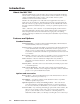
Introduction About the MLC 206 The Extron MediaLink™ Controller (MLC 206) provides infrared (IR) and RS-232 remote control of a display device, contact closure control of items in a room, tally outputs, and MediaLink Switcher control. Some models of Extron system switchers can also be slaved to the controller. The MLC 206 is designed for use with audiovisual equipment in sites such as a small classroom or boardroom.
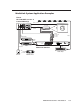
MediaLink System Application Examples Extron MLC 206 AAP Controller & Control Module(s) Relay Control VCR CONTROL REW PLAY Tx FWD PAUSE NEXT PAUSE STOP DISPLAY POWER DVD VOLUME VCR Projector Portable PC MAX/ DVD CONTROL MIN REW PLAY Tx Extron STOP RS-232 Control MLC 206 AAP MediaLink Controller RGB Composite S-video Control IR Emitter Audio Audio/ Video DVD DVD VCR TUNER MAC WORK CELL DOC CAMERA 5 6 MENU NEXT VOLUME ADJUST 1 VCR 2 3 4 Extron MediaLink Switcher DVD
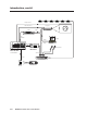
Introduction, cont’d Relay Control Projector RS-232 Control VCR Video Audio IR Emitter Laptop Video Audio SCREEN POSITION DOWN STOP UP RS-232 DISPLAY POWER VCR AUX. VIDEO IMAGE MUTE PC AUX.
MediaLink™ Controllers 2 Chapter Two Installation Installation Overview UL Requirements Installation Procedures
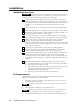
Installation Installation Overview CAUTION Installation and service must be performed by authorized personnel only. UL Listed electrical boxes are recommended. See “UL Requirements” below. To install and set up a MediaLink Controller, follow these steps: 1 If applicable, prepare the installation site: cut a hole in the wall/furniture, install the electrical box or mud ring, and prepare the cables. Instructions are included in this manual and/or with the optional faceplate, mounting device, or wall box.
Installation Procedures The MLC can be installed into a wall, a Euro Channel, or furniture, or, if an optional faceplate is used, it can be mounted directly in furniture or an equipment rack. Follow the instructions appropriate to the mounting option you have selected. Templates for optional faceplates are not detailed in this manual. Preparing the site and installing the wall box Choose a location that will allow cable runs without interference. Allow enough depth for both the wall box and the cables.
Installation, cont’d 7a. If you are using a wall box, insert the wall box into the opening, and attach it to the wall stud/furniture with nails or screws, leaving the front edge flush with the outer wall or Wall Stud furniture surface. The illustration applies to all sizes of wall boxes. Wall Box Screws or Nails Flush with Wall Surface Attaching a wall box to a wall stud If attaching the wall box to wood, use four #8 or #10 screws or 10-penny nails. A minimum of 1/2 inch (1.
Replacing labels The backlit input selection labels are inaccessible once the MLC is installed into a wall or furniture. The faceplate must be removed to gain access to the labels. 1. Use a small Philips screwdriver to remove the four faceplate attachment screws, and keep them for later use. 2. Lift the faceplate off the MLC. 3. Lift off the transparent, protective, plastic window that covers the labels. 4.
Installation, cont’d Rear/bottom panel cable connections 1 MLC 206 rear view 2 3 4 5 6 7 MLC 206 bottom view 1 Configuration port — This port is used for system configuration and for loading control files into the MLC. Connect a host computer, third party control system, or a terminal such as a personal digital assistant to the MLC via this rear panel 9-pin HD female RS-232 connector. Commands and drivers can be downloaded into or uploaded from the MLC via this port.
A Modulated IR To IR Broadcaster with Emitter port (#60-272-02) Ground D E +12VDC output MLC IR control port A B C D E IR For the IR Broadcaster with emitter port To the projector's wired remote port (Connector type and pin configurations may vary depending on the projector model.
Installation, cont’d To the MLC 206 Black Grey Purple Blue Green Yellow Orange Red Brown 9 8 7 6 5 4 3 2 1 1 5 UC Cable To the projector Connector Shell Shield Color Pin # 6 9 UC 50', 100', 200' Cable Color Codes Room/relay control connections Relay 1, pin A Relay 1, pin B Relay 2, pin A Relay 2, pin B Relay 3, pin A Relay 3, pin B Normally open (3B) To / from room control equipment Normally open (3A) Normally open (1B) Normally open (1A) Normally open (2B) Relay connector — This 3.
The control modules are Architectural Adapter Plate modules that can be connected to the MLC to control devices such as VCR, tape, or DVD players, or provide limited control of an optional MLS 306/506 Series switcher, or other devices. Up to four control modules (in addition to the IR Link) can be connected to the MLC, though the connector can hold wires for only 2-3 items at a time, so you may wish to daisy chain the control modules together.
Installation, cont’d Extron switcher control connections 6 Contact closure Tally Out(put) connector — To effectively add more A/V inputs to a projector, you aren’t limited to using a MediaLink switcher. If desired, attach an Extron switcher that accepts contact closure control to this 3.5 mm, 6 pole direct insertion captive screw connector. Each pin corresponds to a switcher front panel button. When a tally pin is selected, the pin changes from a high (5V) to a low (0V) state.
If you are not using an optional switcher, connect an external power supply (12VDC, 1 A maximum) to this port to power the MLC as shown in the following diagram. Ground ( ) +12VDC input An external power supply (12VDC, 1A max.) MLC MLS/Power port A B MLS / Power Connecting an MLC 206 to an external power supply Ground all devices Check the power supply’s polarity before connecting it to the MLC.
Installation, cont’d POWER AB MLS100Series Switcher MLC/RS-232 Power Port 3 2 1 INPUTS OUTPUT AUDIO INPUTS L 1 R L 2 R L 3 R L 4 R AUX/MIX MONO CONTROL/ POWER OUT L R A B MLS 103 V 12V .5A MAX MLS 103 V Rear Panel External Power Supply +12VDC input Ground ( ) 250 ft (76.2 m) max. External Power Supply (12VDC, 1A max.
Pinout guide The illustration below summarizes the pin assignments of all of the MLC’s bottom panel connectors that are covered in detail on pages 2-6 to 2-12.
Installation, cont’d Application diagram An example of one way to connect accessories to the controller is shown in the photo below. The Config port is not shown with an RS-232 cable attached because that connection is only required during setup. This system includes an MLC mounted in an optional faceplate (MLM-LAAP) that holds two control modules (IRCMs, ACMs, and/or RCMs), and an additional control module is connected to the upper IRCM and mounted in another location.
Mounting the MLC to an electrical box or mud ring 1. With power disconnected at the source, insert the MLC into the wall or furniture. 2. Mount the MLC to the wall box or mud ring mounting bracket with the provided machine screws (as shown in the following illustrations), or attach it directly to the furniture with wood or metal screws. If the MLC (and any accessories such as control modules or an IR Link) is not mounted to a grounded metal wall box, • Ground each faceplate directly to an earth ground.
Installation, cont’d Mounting the MLC to a wall or furniture 1. Attach the optional lectern mounting faceplate to the MLC with machine screws, as described on page 2-4 in “Replacing faceplates and labels” in this chapter. 2. With power disconnected at the source, insert the MLC into the wall or furniture. 3. Fasten the MLC and faceplate directly to the furniture or wall using wood screws.
Mounting the MLC in a Euro Channel 1. With power disconnected at the source, insert the MLC 206 EC or MLC 206 AAP EC into the Euro Channel. For wider types of Euro Channels, you may need to insert a spacer plate first. 2. Mount the controller to the Euro Channel by attaching the faceplate to the two backing plates using four #4-40 mounting screws. See the illustration below.
Installation, cont’d 2-18 MediaLink Controllers • Installation
MediaLink™ Controllers 3 Chapter Three Operation Projector Control Front Panel Features and Operation Optional Control Modules and MLA Remote
Operation Projector Control The MLC 206 can control a projector or other display device by using IR or RS-232 control. The MLC must be configured for projector control in one of the following ways before it will send commands to the projector: • An IR or an RS-232 driver file can be downloaded from a disk or the Extron Web site into the MLC. • RS-232 command strings can be entered directly from a host computer using the supplied Windows-based software.
The MLC 206 is shown in the following examples, but the features and operation are the same for all MLC models. 1 DISPLAY POWER 2 VCR DVD Laptop VOLUME 3 MAX/ MIN 4 Extron MLC 206 MediaLink Controller 1 DISPLAY POWER 1 Input selection buttons and backlit labels — From the upper left to lower right these buttons are numbered 1 through 6. See chapter 2 for instructions on how to replace the labels.
Operation, cont’d pressing the button when the MLC is in the secondary mode or via the Windows-based software. The corresponding label flashes when a command associated with a button is executed. Relay triggering — A relay can be associated with a button. The relay can be triggered by pressing a button only when the MLC is in primary mode, or it can be triggered via the control software. See pages 2-8, 4-3, 4-5, 4-10, 4-12, 4-22, and the note on page 4-18 for details.
either an input selection button or display power-up or display powerdown. See chapter two for information on the relays, and see chapter four and the control software for details on changing settings for the relays. Additional and secondary functions — While the secondary mode is active, the Display Power LED blinks rapidly. 3 Volume adjustment knob and LED — Rotate this knob to adjust the audio volume. The LED lights when the volume has reached the minimum or maximum limit.
Operation, cont’d The buttons on the optional MLA-Remote duplicate the MLC’s front panel controls and also those of two Control Modules (IRCMs) for normal operation. The MLA-Remote can also be used to control a MediaLink Switcher (MLS). The controller, control module, or switcher responds to commands from the MLA-Remote as if the corresponding button or knob were pressed or turned on the controller or switcher.
MediaLink™ Controllers 4 Chapter Four Serial Communication RS-232 Programmer’s Guide Control Software for Windows
Serial Communication The MLC can be remotely set up and controlled via a host computer or other device (such as a control system) attached to the rear panel Configuration port. The control device (host) can use either Extron’s Simple Instruction Set (SIS) commands or the graphical control program for Windows. The MLC uses a protocol of 9600 baud, 1 stop bit, no parity, and no flow control.
E16 – Unit is busy E23 – Checksum error. Using the command/response tables The command/response tables below and on the following pages list valid command ASCII codes, the MLC’s responses to the host, and a description of the command’s function or the results of executing the command. Upper and lower case characters may be used interchangeably in the command field. The ASCII to HEX conversion table at left is for use with the command/response tables.
Serial Communication, cont’d Command/response table for SIS commands (continued) Command ASCII Command Response (host to MLC) Additional description (MLC to host) Volume adjustment Set the output volume X3 V Example: Increment (increase audio output) 82V +V Vol Specify the volume for the audio output. Example: set volume to 82. Increment projector’s audio output (if set for projector audio increment/decrement mode). Increase projector’s or switcher’s audio output.
The syntax for setting a special function is __ * X? # where __ is the function number and X? is the value. To view a function’s setting, use __#, where __ is the function number. In the following table the values of the X? variable are different for each command/function. These values are given in the rightmost column.
Serial Communication, cont’d Command/response table for special function SIS commands, continued Command ASCII Command Response X? (host to MLC) (MLC to host) and additional descriptions values AudMute* 0 = no (audio doesn’t mute when display power is off or unmute when display power is on). 1 = yes (default) (audio mutes when display power is off, audio unmutes when display power is on). Example: set audio to mute when display powers off.
Command/response table for special function SIS commands, continued Command ASCII Command Response X? (host to MLC) (MLC to host) and additional descriptions values DVA_VMap* X? Associate specific MLC buttons with the VCR and DVD halves of the IRCM-DV+ which has DIP switch-based addresses of 1 and 2. Associate MLC button 4 with IRCM-DV+ address 1 (DVD functions) and MLC button 3 with IRCM-DV+ address 2 (VCR functions). See the illustration.
Serial Communication, cont’d Command/response table for advanced instructions (for the Windows-based control program) Data downloads/uploads are initiated by sending a series of hex commands to the host RS-232 port of the MLC. The Windows-based control program uses these commands mainly to load and save driver data and system configuration settings. Command Hex.
Control Software for Windows® The included Extron MediaLink™ Control Program for Windows offers another way to control the MLC via RS-232 connection in addition to the Simple Instruction Set™ commands. The control program’s graphical interface includes the same functions as those on the switcher’s front panel and some additional features that are only available through the Windows-based software. The control software must be used in order to download projector driver files into the MLC controller.
Serial Communication, cont’d User Mode The User Mode screen, shown below, includes the most frequently used controls: it emulates the MLC 206 front panel for primary mode functions (input selection, projector power control, volume control, relay toggling), and it emulates the MediaLink Control Modules. See chapter two of this manual and refer to the MediaLink™ Control Modules User’s Manual for details on basic operation.
Switcher (MLS) Config The Switcher (MLS) Config screen, shown below, only becomes available if an optional MediaLink Switcher is connected to the MLC. It allows you to make switcher-specific adjustments without having to use the switcher’s front panel controls. In this part of the program you can: • Set per-input audio adjustments (level, bass, treble). • Set overall volume. (Selecting Mute selects audio input 0.) • Set the left-right audio balance. • Set the mixer volume (MLS 506MA & MLS 506SA only).
Serial Communication, cont’d Controller (MLC) Config The Controller (MLC) Config screen, shown below, is the most important part of the MediaLink Control Program. This is where you configure the controller and the control modules, and initiate IR learning. A green dot in the middle of a button indicates that RS-232 codes have been associated with that button. A red dot indicates that IR codes are associated with/ learned for that button.
Primary and secondary modes The MLC Buttons area in the lower left of this screen lets you select between primary and secondary modes. A button can have one code stored in its memory for primary mode, and another code stored for secondary mode. In each mode the MLC’s buttons can be given an on-screen label: select an option from the pull-down menu above/below each button, as shown at right. If desired, you can change the label name during IR Learning or in the Advanced Projector Config screen.
Serial Communication, cont’d IR learning The MLC can “learn” commands in order to control the projector or to control devices such as VCRs, audio tape players, or DVD players. For the MLC 206, IR learning is only necessary if there are no RS-232 codes available for that projector or if you need to customize the driver. For the infrared control modules, IR learning is essential for setting up the buttons so you can control the VCR, DVD player or other device. To initiate IR learning, 1.
During IR learning hold the device’s remote control 4” to 14” (10 cm to 36 cm) away from and directly in front of the MLC’s IR pickup device. You may need to experiment to determine the best IR learning distance for each remote control. Once the IR commands have been successfully learned, you will have the opportunity to accept a default label or type in your own label (which will appear in the control program screens) for that button. 10.
Serial Communication, cont’d Macros: associating MLC and control module buttons with each other Basic configuration, covered in the rest of this chapter, will meet your needs for most installations. In a standard installation a single control command is sent each time an MLC front panel button (in primary or secondary mode) or control module button is pressed, or the Volume knob is turned. Pressing an input selection button also causes a channel change (input X to input Y).
4. Select a “trigger” button that has been programmed with IR code (shown in dull red) or RS-232 code (shown in green). This is the button you want to push to trigger both button’s commands. Hold the mouse button down as you drag the trigger button across the screen to the desired “destination” button, then release it. The selected trigger and destination buttons turn yellow, and both buttons display the number of the destination button.
Serial Communication, cont’d The trigger and destination buttons change to lighter shades of green or red once they have been associated with each other. Tied buttons can be identified by their lighter shade of red or green, and by the destination button number displayed on the tied trigger and destination buttons. In the example above, pressing the MLC’s input button 1 will also cause the VCR Play command to be issued.
8. You can daisy chain trigger-destination ties together to allow multiple control commands to be sent as a result of one button press. For example, you could tie the PowerOn button to the TV/VCR button of a DVD control module 1 , and then tie the DVD TV/VCR button to the TV/VCR button of a VCR control module 2 , as shown in this example: 1 2 Now when someone presses the PowerOn button, the projector and the DVD player and VCR will all be sent commands to prepare them for use.
Serial Communication, cont’d Advanced Projector Config The Advanced Projector Config screen, shown below, provides a way to check the kind, length, and location of codes (IR/RS-232), if any, that are stored in the memories for the various MLC and control module buttons. In this screen you can also edit or enter RS-232 codes, define step parameters for controlling a projector’s audio volume, and change the name of the projector driver.
to use for asking for the power status (the polling command), the off reference response (for Off Compare), and the on reference response (for On Compare). Refer to the control program’s help file for step-by-step programming instructions. For power polling to be used, you must also select (check) the “Use Projectorpower Polling” box in the Misc. Options part of the Relay & Misc Options portion of the control program (shown on page 4-22).
Serial Communication, cont’d 4. Select “step 2” by using the Current Step scrollbar or box, then edit the RS-232 string as needed to customize it for the next volume command. 5. Repeat step 4 for each “step” in the volume table. 6. The Exit Program button in the lower right corner of the screen is replaced by the Cancel and Take buttons. To save the changes, click on Take. To ignore the changes, click on Cancel.
Latched/Momentary — Contacts can be programmed to operate in one of two ways: latching (brief contact) (press to turn on, press to turn off), or momentary (timed) (press to turn on, timeout to turn off). If you select Momentary, you can set the timeout period by using the slider bar. NC (open), NO (closed) — Select the appropriate box to make the relay normally closed or normally open.
Serial Communication, cont’d Saving and restoring configurations The MLC can be configured by various means (IR learning, downloading, or combinations of those methods), and the configuration settings can be saved to a file for later use. 1. In the MediaLink Control Program, select File, then select Save Configuration as... . 2. Save the file as (filename).MLK. An unlimited number of configuration files can be saved as long as each file has a unique file name ending in .MLK. 3.
Key to file names File name Description ________.MLL Extron-supplied projector driver library files. These files contain commands and settings pertinent to a particular projector. ________.MLK User-saved MLC/MLC-MLS/MLS configuration file. This includes adjustments/settings and whatever driver (if any) was installed in the MLC at the time the file was saved.
Serial Communication, cont’d Using the emulation mode The MediaLink Control Program features an emulation mode so you can set up a MediaLink system before equipment is available on site. In emulation mode a MediaLink Controller is always included in the system. You select which (if any) MLS switcher and which control modules (if used) will be connected to the MLC. You can save the emulated settings to a configuration file, then load that configuration file to the MLC when equipment is available. 1.
4. Enter a filename of your choice for storing the configuration settings, then select Save. The Emulation Configuration dialog box appears, as shown below. 5. Select the MediaLink equipment that will be part of the system you want to configure, then click on OK. The Extron MediaLink Control Program windows appear. 6. Select the desired settings in each section of the program. In emulation mode you cannot perform IR learning. You must have an MLC connected to the host computer for IR learning. 7.
Serial Communication, cont’d 4-28 MediaLink Controllers • Serial Communication
MediaLink™ Controllers A Appendix A Specifications, Part Numbers, and Accessories Specifications Part Numbers and Accessories
Specifications, Part Numbers, Accessories Specifications Control/remote — controller Serial control port ........................ Baud rate and protocol ............... Serial control pin configurations Slave switcher control port ........ Program control ........................... RS-232, 9-pin female D connector 9600, 8-bit, 1 stop bit, no parity 2 = TX, 3 = RX, 5 = GND (1) 3.
Part Numbers and Accessories Included parts These items are included in each order for an MLC 206 controller: Included parts MLC 206 (3-gang) (gray, black, white) Replacement part number 60-385-01, -02, -03 or MLC 206 AAP (5-gang) (gray, black, white) 60-460-01, -02, -03 or MLC 206 EC (white) 60-385-10 or MLC 206 AAP EC (white) 60-460-10 IR Emitter 12VDC, 1 A power supply kit 70-055-01 IEC power cord UC 50’ (15 m) universal projector control cable 26-518-01 9-pin male-to-male gender changer
Specifications, Part Numbers, Accessories, cont’d Miscellaneous accessories Part number MLA-Remote IR remote control 70-154-01 IR Link IR signal repeater (gray, black, white) IR Broadcaster 60-404-01, -02, -03 60-272-01 Current/display power sensor 60-271-01 IRCM-VCR (gray, black, white) 70-148-01, -02, -03 IRCM-DVD (gray, black, white) 70-149-01, -02, -03 IRCM-DVD+ (gray, black, white) 70-179-01, -02, -03 IRCM-Tape (gray, black, white) 70-180-01, -02, -03 IRCM-DV+ (gray, black, white) 70-2
MediaLink™ Controllers B Appendix B Dimensions, Templates, Replacements, and Upgrades Dimensions Templates Replacements and Upgrades
Dimensions, Templates, Replacements, Upgrades Dimensions The following diagrams have been reduced to fit on the page. All dimensions are given in inches. The symbol “ø“ indicates a diameter.
Templates Use the full size template below (MLC 206) or on the next page (MLC 206 AAP) or a 100% size photocopy of the template as a guide for cutting a hole in a wall or furniture for installing the MLC. Cut out the appropriate dashed or dotted inner rectangle of Wall Stud the template, lay the template against the installation surface (wall/furniture), and mark the opening on Screws or Nails the surface. The controller requires a depth of at least 1.25” (3.2 cm) inside the wall or furniture.
B-4 The light grey area with the solid grey line indicates the location of the MLC The dashed line indicates the cut-out area (3.9" H x 9.5" W) for installing the electrical wall box. MLC 206 AAP Cutout Template The medium grey area represents the layout of the electrical box (3.75" H x 9.3" W) against the rear of the front panel. To install the MLC 206 AAP directly into furniture, use the cut-out area (2.8" H x 8.8" W) indicated by the dotted line.
Replacements and Upgrades Firmware replacement In some cases the MLC’s firmware may require replacement with an updated version. We recommend that you send the unit in to Extron for service and updates. Changes to firmware must be performed by authorized service personnel only. CAUTION Follow these steps to replace firmware in the MLC 206. 1. Disconnect the power supply from the power source. To prevent electric shock, always unplug the MLC from the power source before opening the enclosure. 2.
Dimensions, Templates, Replacements, Upgrades, cont’d A B C Dis IR D E pla A B y/S ou RSC D rce -23 E Co 2 ntr ol 1A 1B 2A Re 2B 3A lay s 3B A IR B C D /R CM 1 2 3 33-644-01 A 07 01 Printed in the USA Ex Tally 4 5 tro Ou 6 nS t A wit M B ch LS/P er ow Co er ntr ol Align Notches Locating the firmware IC chip, and aligning the PLCC chip puller tool with firmware chip slots 5.
FCC Class A Notice Note: This equipment has been tested and found to comply with the limits for a Class A digital device, pursuant to part 15 of the FCC Rules. These limits are designed to provide reasonable protection against harmful interference when the equipment is operated in a commercial environment. This equipment generates, uses and can radiate radio frequency energy and, if not installed and used in accordance with the instruction manual, may cause harmful interference to radio communications.
www.extron.com Extron Electronics, USA Extron Electronics, Europe Extron Electronics, Asia Extron Electronics, Japan 1230 South Lewis Street Anaheim, CA 92805 USA 714.491.1500 Fax 714.491.1517 Beeldschermweg 6C 3821 AH Amersfoort The Netherlands +31.33.453.4040 Fax +31.33.453.4050 135 Joo Seng Road, #04-01 PM Industrial Building Singapore 368363 +65.6383.4400 Fax +65.6383.4664 Daisan DMJ Building 6F 3-9-1 Kudan Minami Chiyoda-ku, Tokyo 102-0074 Japan +81.3.3511.7655 Fax +81.3.3511.