
Instruction Manual


5-17MLC 104 Series • SIS
™
Programming and Control
PRELIMINARY
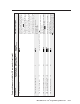
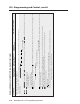
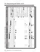
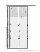
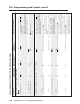
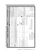
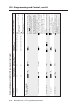
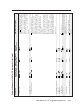
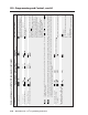
Command/response table for SIS commands (continued)
Command ASCII (Telnet) URL Encoded (Web) Response Additional description
(host to switcher) (host to switcher) (switcher to host)
Query updated firmware version 4Q 4Q
X11
(kernel version–model description–date time of upload)
Use this command to find out which version
of the firmware, if any was uploaded into
the controller after it left the factory.
Example: 4Q 4Q 1.00*(1.18-MLC104 -Thu, 15 Sep 2005 22:42:14 GMT)
In this example the current firmware version
is 1.00, the IP Link kernel version is 1.18, for
the MLC 104, dated 15 September, 2005.
In a query response, an asterisk (*) after the version number indicates the version that is currently used.
A question mark (? or ?.??) indicates that the factory default firmware is the only firmware loaded in the switcher.
A carat (^) indicates the version of firmware that should be running, but, since a mode 1 reset was performed, the factory default firmware version is loaded and running instead.
An exclamation point (!) indicates that the firmware is corrupted.
Query FPGA version 32Q 32Q
X11
Show the field-programmable gate array
(FPGA) firmware version to two decimal
places (x.xx).
Request the MLC’s part number N N 60-xxx-00
Show the MLC’s part #. 60-573-00 =
MLC 104 IP, 60-665-00 = MLC 104.
Request A/V input number I I Chn
X200
Show which input is active (selected).
X200
is the input number.
Request the model name 1I 1I MLC 104 IP
or MLC 104
Request the model description 2I 2I MLC 104 w/ IP MLC 104 with IP control.
Request system memory usage 3I 3I # bytes used out of # of kbytes Show amount of memory used and total
available memory for system operations.
Request user memory usage 4I 4I # bytes used out of # of kbytes
Show amount of user memory used and
total available user memory.
Example: 4I 4I 217856 Bytes Used out of 7232 KBytes
Request status of attached hardware 32I 32I P1##•P2##•K1##•K2##•K3##•K4##•S
Show the absence of or types of connected
devices.
For ##:
00 = not present
* 00 is the value (##) for K1, K2, K3, and K4 for
the MLC 104 Series because they do not support
control modules (IRCMs, ACMs, CCs, RCMs)
For :
00 = not present
01 = MLS 306
02 = MLS 506
03 = MLS 506 MA 70 V
04 = MLS 506 SA
05 = MLS 506 MA 100 V
06 = MLS 100 A
07 = MLS 103 V
Prefixes for connected devices:
P1 = SCP #1, address 0
P2 = SCP #2, address 1
K1 = control module #1, address 0*
K2 = control module #2, address 1*
K3 = control module #3, address 2*
K4 = control module #4, address 3*
S = MediaLink device, typically
a slaved MLS switcher.
08 = MLS 103 SV
09 = MLS 102 VGA
10 = MLA-VC10
11 = MLS 304 MA
12 = MLS 406
13 = MLS 406 MA
14 = MLS 406 SA
15 = MLS 304 SA