MLC 104 MediaLink™ Controllers 5 Chapter Five SIS™ Programming and Control Host-to-MLC Communications Command Tables
SIS™ Programming and Control The MLC 104 Series controller can be remotely set up and controlled via a host computer or other device (such as a control system) attached to the rear panel Config/RS-232 port or LAN port, or the front panel Config port. The MLC 104 or MLC 104 IP must be configured before use. As shipped the controller can trigger basic input switching but cannot control any other devices before being configured.
• If the MLC is on, it sends the boot and copyright messages when you first open a Telnet connection to the MLC. You can see the day of the week, date, and time if the MLC is connected via Telnet, but not via RS-232. If you are using a Telnet connection, the copyright message, date, and time are followed by a password prompt. C hn X1 (where X1 is the input number) The MLC sends this response when an input is switched.
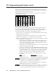
SIS™ Programming and Control, cont’d RS-232. The ASCII and URL commands listed in the tables starting on page 5-8 perform the same functions, but they are encoded differently to accommodate the requirements of each port (Telnet or browser). The following ASCII to hexadecimal (HEX) conversion table is for use with the command/response tables.
X17 = = CR/LF (carriage return/line feed) (hex 0D 0A) = Carriage return (no line feed, hex 0D) (use the pipe character, | , instead for Web browser commands) • = Space character | = Esc = X1 X2 = = Specific port number or relay number (01 – 99) represented as two ASCII characters (two bytes) Ports: 01 = rear host (Config/RS-232 port) 02 = front panel Config port 03 = slaved switcher (MLS port) 04 = projector port (Proj RS-232/IR) X3 = Greenwich Mean Time (GMT) offset value (-12.00 to +14.
SIS™ Programming and Control, cont’d X25 = Baud rate: 300, 600, 1200, 1800, 2400, 3600, 4800, 7200, 9600, 14400, 19200, 28800, 38400, 57600, or 115200 X49 = Default name: a combination of the modelname and the last 3 pairs of the MLC’s MAC address (e.g., MLC-104-IP-00-02-3D) X26 = Parity (only the first letter is needed): Odd Even None (default) Mark Space X51 = Extended-security (password) levels (1 to 10). The response will be two digits with a leading zero.
= Display (projector on/off) status as tracked by the display driver 0 = display power is off 1 = display power is on 2 = display is powering down/off (cooling down) 3 = display is powering up/on (warming up) X209 = Front panel lockout (executive mode ) status 0 = off/unlocked (default) 3 = on, disable/lock entire front panel (buttons, volume control) and optional connected SCP X210 = IR/serial port configuration 0 = IR ports (0 V – 5 V) (default) 1 = RS-232 ports (±5 V) X211 = Status (in hexadecimal
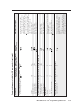
5-8 MLC 104 Series • SIS™ Programming and Control Turn display mute on Turn display mute off View display mute status Set mute status Display mute 1M 0M M X216 %2A0M 1M 0M M X216 *0M X208 %2A0P X208 *0P Set power status X200 %21 1P 0P P P ! URL Encoded (Web) (host to switcher) 1P 0P P P X200 (host to switcher) ASCII (Telnet) Turn display power on Turn display power off View display power status Example: Display (projector) power Select an input14, 22 Input selection Command Command/resp
MLC 104 Series • SIS™ Programming and Control 5-9 URL Encoded (Web) (host to switcher) ASCII (Telnet) (host to switcher) V 27V %2BV %2DV V X8 0Z Z Mute off View the audio mute status 0Z Z 1Z %2BV %2DV V Disable lockout modes24 0X 0X Front panel security lockout modes (executive modes) 1Z +V -V V Mute on Audio mute Increment the volume Decrement the volume View the volume level X8 Exe 0 X5 Amt0 Amt1 Vol+ Vol--- X8 Vol027 Vol X8 Vol X8 Vol (switcher to host) Response PRELIMINARY
5-10 ASCII (Telnet) X205 %2A X205 %2A 6S 7S X205 *6S X205 * X205 *6S 7S X216 *7S Set lamp hours status for 1 lamp24 Set lamp hours status for 2 lamps24 View connection status Set projector connection status24 MLC 104 Series • SIS™ Programming and Control X216 %2A 7S X205 %2A 6S 6S 6S X 3X (host to switcher) URL Encoded (Web) View lamp hours status Status commands X X View the lockout mode status Example: 3X (host to switcher) Enable lockout mode 324 Command Command/response table
MLC 104 Series • SIS™ Programming and Control 5-11 14S 16S 20S 12S View +12 V power supply voltage View +3.3 V IP Link/FPGA voltage 14S View -10 V IR/Serial bus voltage 16S View internal temperature status 20S 12S 11S 11S 9S View all voltage & temp. status 9S View power sensor signal pin status 8S Additional description If the switcher is connected to an Extron Power Sensor that monitors the projector/ display, this tells you whether the display is still powered on.
5-12 ASCII (Telnet) (host to switcher) (host to switcher) URL Encoded (Web) (switcher to host) Response Additional description MLC 104 Series • SIS™ Programming and Control Examples: A 3-byte length = 3L. A delimiter of ASCII 0A = 10D. X1 = specific port number (01 – 99) 01 = rear host (Config/RS-232 port) 02 = front panel Config port 03 = slaved switcher (MLS port) 04 = projector port (Proj RS-232/IR) X2 = command data section.
MLC 104 Series • SIS™ Programming and Control 5-13 View receive timeout View serial port parameters Configure receive timeout24 Example: Configure serial port parameters24 Command X1 X20 , X23 , X21 PRELIMINARY X17 , X20 , X23 , X21 W X1 CE | CE X1 * X17 * X20 * X23 * X21 Esc X1 Esc X25 , X26 , X27 , X28 W X1 CP | CE W X1 %2A X17 %2A X20 %2A X23 %2A X21 CE | Cpn X1 •Cce X17 , W4%2A9600%2CN%2C8%2C1CP | Cpn4•Ccp9600,N,8,1 CP 4*9600,N,8,1CP Esc Esc (switcher to host) Response W X1 %2A
5-14 ASCII (Telnet) Esc X215 , X57 , X58 , X59 (host to switcher) MLC 104 Series • SIS™ Programming and Control Esc Example: POWER E13 W3%2C1IR | W3%2C2IR | 3,1IR 3,2IR View an IR/Serial port’s config. Configure an IR/Serial Out port24 Esc 1 IC Esc X215 IC Esc X215 * X210 IC Irc X210 01 W X215 %2A X210 IC | W X215 IC | W1 IC | X215 * X210 {descriptive text} IR W X57 %2C X58 IR | X57 , X58 An IR driver must be loaded into the MLC before IR command information can be read.
MLC 104 Series • SIS™ Programming and Control 5-15 URL Encoded (Web) (host to switcher) ASCII (Telnet) (host to switcher) View current port’s timeout period Esc View global IP port timeout period Set current port’s timeout period24 Esc Esc Esc Set global IP port timeout period24 W1TC | W0%2A X69 TC | W0TC | 1TC 0* X69 TC 0TC X69 Pti 0* X69 X69 Pti 1* X69 (switcher to host) Response PRELIMINARY W1%2A X69 TC | 1* X69 TC Ethernet data port configuration and use Command Command/respons
5-16 ASCII (Telnet) (host to switcher) (host to switcher) URL Encoded (Web) MLC 104 Series • SIS™ Programming and Control 2[ 2] View the digital input mode View the digital input state X40 [ 2%5B 2%5D 2%2A X40 %5B Q or 1Q 3Q 2Q 3Q Example: Query factory firmware version Example: 2Q Query bootstrap firmware version 0Q Example: 1Q Query verbose version information 0Q Query firmware version number 3Q 2Q 3Q 2Q 0Q 1Q 0Q Q or 1Q Firmware version, part number & information requests 2* Set
MLC 104 Series • SIS™ Programming and Control 5-17 1I 2I 3I 4I Request the model name Request the model description Request system memory usage Request user memory usage 32I 4I 4I 1I 2I 3I I N 32Q Prefixes for connected devices: P1 = SCP #1, address 0 P2 = SCP #2, address 1 K1 = control module #1, address 0* K2 = control module #2, address 1* K3 = control module #3, address 2* K4 = control module #4, address 3* S = MediaLink device, typically a slaved MLS switcher.
5-18 ASCII (Telnet) Esc Esc Esc Esc Set unit name to factory default24 Read the unit name Set time/date24 MLC 104 Series • SIS™ Programming and Control Read time/date X12 Ipt• X13 X13 WCN | W X13 CT | WCT | CN CT CT Ipn• X49 W%20CN | •CN X13 Ipn• X12 CN Additional description or X49 Change the MLC’s name to one of your choosing ( X12 ), such as “AuditoriumMLC”, “Rm316-AVcenter”, or “exec-boardroomctrl”. The name consists of up to 24 alphanumeric characters (and the minus sign).
MLC 104 Series • SIS™ Programming and Control 5-19 Read hardware address (MAC) Read IP address Esc Esc Esc Esc Esc Esc Esc CH X18 X5 X14 PRELIMINARY WCH | X14 WCI | CI X34 X34 Idh 1 Idh 0 Ipi• WCX | W1DH | W0DH | WDH | Ipx WCZ | W X34 CX | X3 X3 Ipz W X3 CZ | W X14 CI | CX CZ (switcher to host) Response CX 1 DH 0 DH DH X14 CI X34 Esc Read daylight saving time Set DHCP on24 Set DHCP off24 View DHCP mode Set IP address24 CZ Esc Read GMT offset Set daylight saving time24
5-20 ASCII (Telnet) CG CV CG CS WCG | W X22 CV | WCS | W X14 CG | W X19 CS | (host to switcher) URL Encoded (Web) X14 X19 MLC 104 Series • SIS™ Programming and Control X19 = subnet mask (xxx.xxx.xxx.xxx). Syntax is the same as for IP addresses. Leading zeros are optional in setting values. Leading zeros are suppressed. X14 = IP address (xxx.xxx.xxx.xxx).
MLC 104 Series • SIS™ Programming and Control 5-21 X33 CA W X33 CA | (host to switcher) Esc URL Encoded (Web) ASCII (Telnet) (host to switcher) Ipa• X41 (switcher to host) Response Additional description Esc Clear user password24 Read user password Esc Esc Esc CA CU •CU CU X33 WCA | W X33 CU | X41 X41 Ipu• PRELIMINARY W%20CU | WCU | Ipu• X41 This clears the user password only. Set the user password ( X33 is 4 to 12 alphanumeric characters). The password is case sensitive.
5-22 ASCII (Telnet) (host to switcher) (host to switcher) URL Encoded (Web) (switcher to host) Response Additional description MLC 104 Series • SIS™ Programming and Control Disable the Direct Access port24 Read the Direct Access port map Read the Telnet port map Set the Web port map24 Reset the Web port map24 Disable the Web port map24 Read the Web port map Set the Direct Access port map24 Reset the Direct Access port map24 Esc Reset the Telnet port map24 Disable the Telnet port map24 Esc Esc Es
MLC 104 Series • SIS™ Programming and Control 5-23 directorypath/ CJ W directorypath%2F CJ | (host to switcher) Esc URL Encoded (Web) ASCII (Telnet) (host to switcher) Dir•directorypath/ (switcher to host) Response The directory’s name must be composed of alphanumeric characters and may include the minus sign (hyphen, -). The first character must be a letter. Case does not matter. No blank or space characters are permitted in the name. Include the full path, not just the name of the directory.
5-24 ASCII (Telnet) (host to switcher) Del • filename Ddl Ddl W%2F EF | W%2F%2F EF | (switcher to host) Response Wfilename EF | (host to switcher) URL Encoded (Web) Additional description MLC 104 Series • SIS™ Programming and Control Example (via Telnet or Hyperterminal): Esc DF WDF | 4.evt Tue, 01 Mar 2005 02:03:07 GMT 42233 1.eml Tue, 01 Mar 2005 02:03:34 GMT 200 2.eml Tue, 01 Mar 2005 02:03:34 GMT 300 2.eir Tue, 01 Mar 2005 02:03:34 GMT 1683 6.evt Tue, 01 Mar 2005 02:03:36 GMT 17956 4.
MLC 104 Series • SIS™ Programming and Control 5-25 URL Encoded (Web) (host to switcher) ASCII (Telnet) (host to switcher) (See responses to Esc (switcher to host) Response DF , above. The response is the same except that the path/directory preceds filenames for files within the subdirectories.
5-26 ASCII (Telnet) (host to switcher) X14 , X15 CM MLC 104 Series • SIS™ Programming and Control Esc Esc Esc 1AE 0AE AE CM X14 %2C X15 W1AE | W0AE | WAE | W CM | W CM | X45 X45 X15 The response is the quantity of currently running events, and it includes leading zeros. For example, if two events are running, the response is 00002 . X14 = IP address (xxx.xxx.xxx.xxx). Leading zeros are suppressed in returned values. X15 = E-mail domain name, e.g., extron.com X14 = IP address (xxx.xxx.xxx.
MLC 104 Series • SIS™ Programming and Control 5-27 URL Encoded (Web) (host to switcher) ASCII (Telnet) (host to switcher) Change the Power On and Power Off buttons' functions from firmware control to script control. Example: Input 6 Input 1 Input 2 W X211 LZ | Hex Nibble Hex Nibble Power Off Power On 0 0 Convert binary to hexadecimal. 00000#0# 00000003 Add 5 leading zeros for a total of 8 characters. Insert number into command.
5-28 MLC 104 Series • SIS™ Programming and Control ASCII (Telnet) (host to switcher) 0 0 Power Off Power On F WLZ | 0 3 1 1 1 1 0 0 0 0 0 0 1 1 Input 1 Input 2 Input 3 Input 4 C X211 Convert binary to hexadecimal. Convert binary to hexadecimal. Insert number into command. 00000F03 Insert number into command. Add 5 leading zeros for a total of 8 characters.
MLC 104 Series • SIS™ Programming and Control 5-29 Input 4 Light buttons: • Power On = amber • Power Off = red • Inputs 1, 2 = amber • Input 3 = green • Input 4 = red Example Input 1 Power Off Input 3 Input 2 Hex Nibble Input 1 Hex Nibble Hex Nibble 0 Hex Nibble 0 Hex Nibble 0 Hex Nibble 9 Hex Nibble F Hex Nibble 0 Hex Nibble 0 Hex Nibble B PRELIMINARY Hex Nibble 0 Convert to hex.
5-30 ASCII (Telnet) (host to switcher) (host to switcher) URL Encoded (Web) Lbk*2* X212 X212 Lbk*1* X212 X212 (switcher to host) Response Additional description Esc ZXXX ZFFF Zpx Zpq WZQQQ | Zpf WZXXX | WZFFF | Absolute system reset24 Esc Esc ZQQQ Reset all settings/memories. The ZQQQ command resets everything (all settings, adjustments, PINs, the IP address, and subnet mask) to the factory default values. Files in flash memory are also erased by this command.
The syntax for setting a special function for an MLC is X? * __ # where X? is the value and __ is the function number. To view a function’s setting, use __#, where __ is the function number. In the following table the values of the X? variable are different for each command/function. These values are given in the rightmost column.
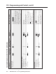
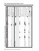
SIS™ Programming and Control, cont’d Command/response table for special function SIS commands, continued Command ASCII Command Response X? (host to MLC) and additional descriptions (MLC to host) values Miscellaneous settings For X? , 0 = disable control of a slaved Extron MLS switcher, 1 = enable (default) MLS slaved switcher control X? *46 # VolMode* X? For X? , Volume knob mode24 0 = discrete volume values 1 = continuous increment/ decrement. X? *47 # Max.
Command/response table for special function SIS commands, continued Command ASCII Command Response X? (host to MLC) and additional descriptions (MLC to host)) values Button press/release emulation Emulating a button press or release causes the commands and actions that are associated with the button via the main event script to be executed. Button emulation triggers only what has been set up via the Button Config. part of the Windows-based configuration program or via Global Configurator 2.
SIS™ Programming and Control, cont’d Command/response table for special function SIS commands, continued Command ASCII Command Response X? (host to MLC) (MLC to host) and additional descriptions values * 3 Y? # SlaveMap Y? * Button control Set slave map24 X? X? values Y? values Default: X? = Y? 1 = input button 1 2 = input button 2 3 = input button 3 4 = input button 4 00 = input 0 01 = input 1 02 = input 2 ...
Command/response table for special function SIS commands, continued Command Front panel button LED control24 Query button LED control status ASCII Command Response X? (host to MLC) (MLC to host) and additional descriptions Lmp is the LED state, is which projector power, input, or room/function button to control. See the list of values at left.
SIS™ Programming and Control, cont’d Command/response table for special function SIS commands, continued Command X? (MLC to host) and additional descriptions Y? For X? ,, 0 = administrator level, 1 = user level. Y? is the corresponding 4-digit PIN.